
ZW7‑40.5
HV Outdoor Vacuum Circuit Breaker
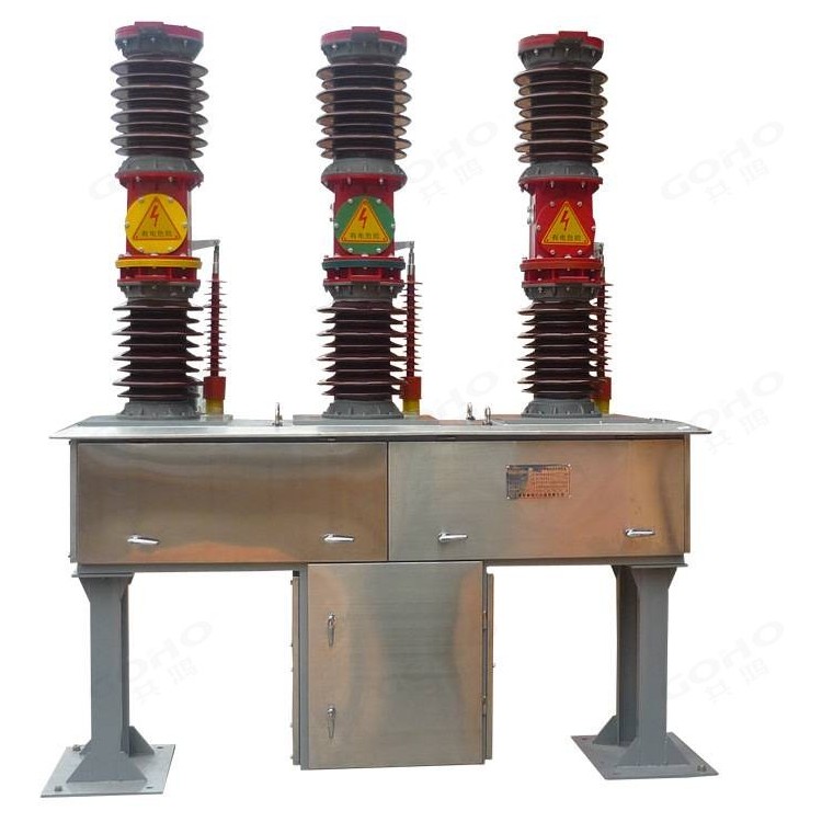
GOHO® builds the ZW7‑40.5 three‑pole outdoor vacuum circuit breaker for 40.5 kV three‑phase distribution networks. The vacuum interrupter sits inside the upper porcelain column and the support column below it carries the live parts, with the linkage sealed inside a weatherproof mechanism housing. It switches load current, overcurrent and short‑circuit current on overhead lines and in distribution substations, and is supplied with optional built‑in current transformers for metering and protection.
- Rated Voltage
- 40.5 kV Three-phase, 50 Hz, outdoor switchgear
- Rated Normal Current
- 630 · 1250 · 1600 · 2000 A One design, four current ratings
- Short-Circuit Breaking
- 20 · 25 · 31.5 kA Peak withstand 50 · 63 · 80 kA, 4 s duty
Technical Specifications
| Parameter | Value |
|---|---|
| Rated voltage Ur | 40.5 kV |
| Rated frequency | 50 Hz |
| Number of poles | 3 |
| Rated normal current Ir | 630 / 1250 / 1600 / 2000 A |
| Rated short-circuit breaking current Isc | 20 / 25 / 31.5 kA |
| Rated short-circuit making current (peak) | 50 / 63 / 80 kA |
| Rated short-time withstand current Ik, 4 s | 20 / 25 / 31.5 kA |
| Rated peak withstand current Ip | 50 / 63 / 80 kA |
| Rated duration of short circuit | 4 s |
| Rated power-frequency withstand voltage, 1 min (dry) | 95 kV |
| Rated power-frequency withstand voltage, 1 min (wet) | 80 kV |
| Rated lightning impulse withstand voltage (peak) | 185 kV |
| Rated operating sequence | O – 0.3 s – CO – 180 s – CO |
| Rated capacitor bank breaking current | 400 A |
| Number of short-circuit breaking operations | 12 |
| Opening time | ≤ 60 ms |
| Closing time | ≤ 150 ms |
| Average opening speed | 1.5 ± 0.2 m/s |
| Average closing speed | 0.7 ± 0.2 m/s |
| Contact bounce time on closing | ≤ 5 ms |
| Three-phase opening / closing asynchronism | ≤ 2 ms |
| Main circuit resistance per phase (excl. current transformers) | ≤ 100 µΩ |
| Permissible contact wear | 3 mm |
| Rated control and auxiliary circuit voltage | DC 220 V / AC 220 V |
| Mechanical endurance | 10 000 operating cycles |
| Weight, complete with operating mechanism | approx. 800 kg |
| Product standard | GB/T 1984 · IEC 62271-100 |
Values above describe the standard ZW7‑40.5 platform and are given as typical ratings. The rating combination of a specific breaker follows the approved drawing, the selected current transformers and the operating mechanism ordered. Ratings outside this table — higher current, other control voltages or site-specific insulation levels — are quoted on application.
Service Conditions
The ZW7‑40.5 is an outdoor device. Its porcelain columns and sealed mechanism housing are designed for direct exposure to weather rather than for an enclosure, so the site conditions below are part of the specification rather than a general note.
| Condition | Limits for standard supply |
|---|---|
| Ambient temperature | −30 °C to +40 °C |
| Daily mean temperature difference | ≤ 32 K |
| Altitude | ≤ 1000 m |
| Wind pressure | ≤ 700 Pa (equivalent to 34 m/s) |
| Air pollution level | Class IV |
| Seismic intensity | ≤ 8 degrees |
| Ice coating thickness | ≤ 10 mm |
Sites outside these limits — high altitude, heavier ice loading, a lower minimum temperature or a different pollution class — are handled by agreement at the enquiry stage, since the external insulation and the mechanism heater are selected against them.
Construction & Operating Principle
Porcelain-column construction
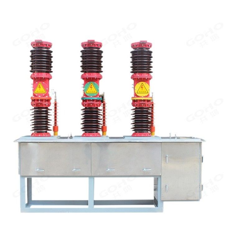
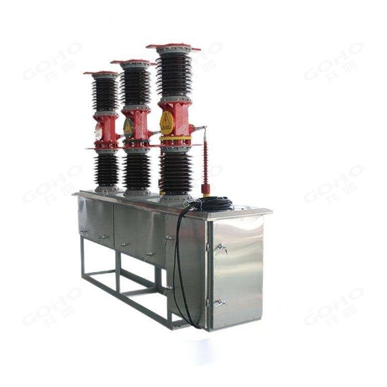
Each pole is built as a vertical column: the vacuum interrupter is housed in the upper porcelain insulator, and the lower porcelain insulator carries the mechanical load as the support column. A cast housing between the two insulators holds the contact linkage, and the three poles are mounted on a common frame above the mechanism box. The insulation therefore lives in porcelain exposed to air — there is no oil tank and no gas compartment to monitor.
Sealed mechanism housing
The operating rod runs from the mechanism box up into each column through a weatherproof transmission housing. Sealing the linkage is what allows the breaker to sit on a pole or a frame in the open: rain, dust and condensation stay outside the housing, and the moving parts are not exposed to the weather. The mechanism box itself is a sheet‑steel enclosure mounted below the frame, carrying the operating mechanism, the auxiliary switches and the terminal block for the control circuit.
How it operates
When the mechanism is tripped, the opening spring drives the output lever and the insulated operating rod; the rod moves the contact linkage in each pole so that the moving contact separates from the fixed contact inside the vacuum interrupter. The arc that forms is extinguished in the vacuum chamber within a fraction of a cycle, and the three poles operate together within the asynchronism limit. Closing reverses the sequence against the closing spring, and the mechanism latches the breaker closed.
Current Transformers & Operating Mechanism
Built-in current transformers
Two or three current transformers can be fitted inside the breaker, one per phase, with four cores per transformer so that metering and protection can be taken from the same unit. Ratios and accuracy classes are selected to the project: a typical arrangement gives a metering core at class 0.2 together with protection cores for overcurrent and earth‑fault duties. Fitting the transformers inside the breaker removes the separate CT pedestal and the extra primary connections that go with it.
Operating mechanism
The breaker is supplied with a spring operating mechanism or an electromagnetic mechanism, matched to the control voltage available on site. Both versions are motor‑charged or energised from the DC or AC auxiliary supply, and both provide manual opening and closing for commissioning. Tripping can be initiated locally, from the control room, or from a sectionaliser or recloser controller where the line is being automated.
Frequent switching duty
Because the arc is interrupted in vacuum rather than in oil, contact life is long and the breaker is suited to circuits that switch often — capacitor banks, line sectionalising points and the incoming feeders of industrial plants. Rated mechanical endurance is 10 000 operating cycles, and the number of rated short‑circuit breaking operations is 12.
Available Ratings & Options
The smallest rating in the range. Used on branch lines feeding a single transformer or a small distribution point, where the continuous current stays low and the duty is mainly load switching.
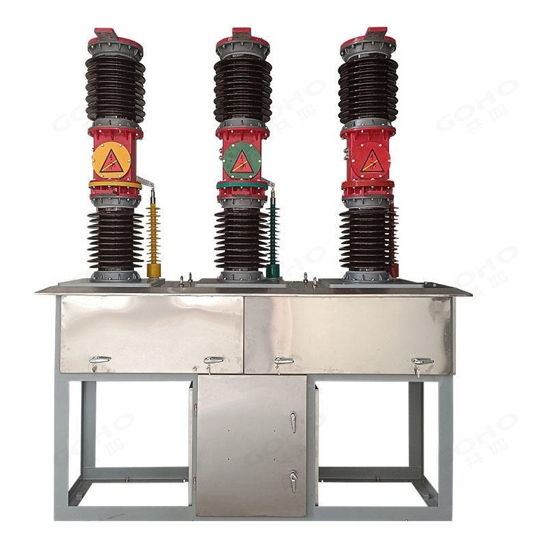
The workhorse rating on 35 kV overhead lines. It covers most urban and rural distribution feeders, and is the usual choice where the feeder loading is not yet settled.
The usual choice for a distribution substation incoming breaker or a bus sectionalising point feeding several outgoing feeders.
For industrial plant incoming feeders and heavily loaded lines expected to grow, normally ordered with the higher 31.5 kA breaking rating where the system short‑circuit level requires it.
| Option | Available |
|---|---|
| Type designation | ZW7-40.5/T (spring mechanism) · ZW7-40.5/D (electromagnetic mechanism) |
| Rated normal current | 630 / 1250 / 1600 / 2000 A |
| Rated short-circuit breaking current | 20 / 25 / 31.5 kA |
| Operating mechanism | Spring mechanism (type T) or electromagnetic mechanism (type D) |
| Current transformers | 2 or 3, four cores per phase, ratio and accuracy class to order |
| Mounting | Pole‑mounted or floor‑standing on a support frame |
| Control and auxiliary voltage | DC 220 V / AC 220 V, other voltages on application |
Key Features
Applications
The ZW7‑40.5 is used wherever a 35 kV class network has to be switched outdoors — on the line itself, at a substation, or at the incoming feeder of a plant.
- 35 kV overhead distribution lines — line sectionalising and isolation
- Distribution substations — incoming and outgoing feeder breakers
- Rural electrification — pole‑mounted switching along the feeder
- Bus sectionalising — tying two busbar sections together
- Capacitor bank switching — frequent operation without contact wear
- Industrial plant incomers — incoming feeders to factory substations
- Wind and solar plants — collector line and plant auxiliary switching
- Railway traction supply — outdoor feeder and sectioning breakers
- Mining and quarry sites — distribution in dusty service conditions
- Oil and gas fields — distribution feeders at remote well sites
- Water and pumping stations — municipal distribution feeders
- Utility feeder automation — breakers combined with recloser controllers
What We Need to Quote Your Breaker
Because each breaker is configured to the project — current rating, breaking capacity, current transformers and mechanism — the enquiry has to carry the electrical duty and the site conditions. With the items below we can return a firm quotation and a dimensional drawing.
- System voltage, rated frequency and earthing arrangement
- Rated normal current required at the breaker
- System short-circuit level, or the required breaking capacity
- Current transformer requirement — quantity, ratio and accuracy class
- Operating mechanism preference and the control voltage available
- Mounting arrangement — pole‑mounted or on a support frame
- Site conditions — altitude, minimum temperature, ice and pollution class
- Quantity, destination and any requirement for a controller interface
Send these to gohointl@gmail.com and we will reply with a priced offer, a dimensional drawing for the foundation and the routine test plan for the breaker.
Standards & Documentation
| Item | Reference |
|---|---|
| Product standard, China | GB/T 1984 — High-voltage alternating-current circuit-breakers |
| Product standard, international | IEC 62271-100 — High-voltage switchgear and controlgear, Part 100 |
| Routine test, main circuit | Main circuit resistance measurement and power-frequency withstand test |
| Routine test, auxiliary circuits | Wiring check and power-frequency withstand test of control and auxiliary circuits |
| Routine test, mechanical | Mechanical operating test over the full open / close sequence |
| Documentation supplied | Dimensional drawing, foundation drawing, circuit diagram, routine test record and operating instructions |
Type test reports for the ZW7‑40.5 platform and the routine test record for the individual breaker are available for project qualification on request.
Breakers are assembled in our own factory in Yueqing, Zhejiang — the same site that builds our switchgear, transformers and prefabricated substations. Porcelain assembly, mechanism fitting, wiring and routine testing all happen in‑house, which keeps both the delivery schedule and the quality check inside our control.
GOHO® is a registered trademark of Gonghong Electric Appliance Co., Ltd. Technical data describes the standard ZW7‑40.5 outdoor vacuum circuit breaker platform; the ratings of a specific breaker follow the approved drawing, the selected current transformers and the operating mechanism ordered. Ratings outside the table in this page, and site conditions outside the stated limits, are quoted on application. Product images are shown for illustration. Please refer to the drawing issued with your offer for dimensional and foundation data.