

ZFS Wind & Solar Combined Prefabricated Substation
GOHO ZFS YB□-40.5/0.69-1600 — purpose-built prefabricated substation for wind and solar power plants. Integrates 40.5kV HV switchgear, step-up transformer, LV distribution, and fiber-optic monitoring in one weatherproof container. 1000–5000kVA with amorphous alloy or S20 low-loss core, IEC 61850 automation, and grid-code compliance for utility-scale renewable energy.


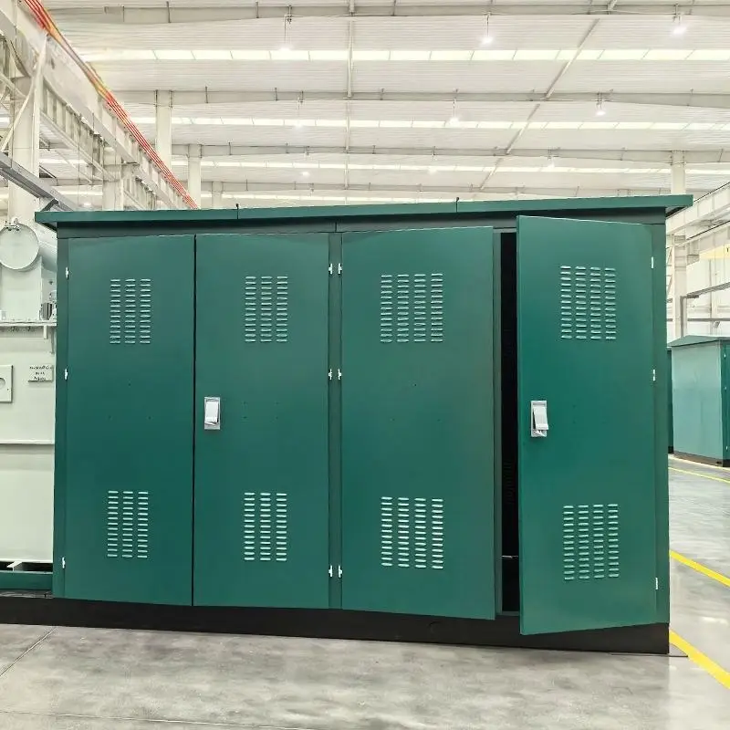


Engineered for Wind & Solar Grid Connection
The all-in-one step-up substation purpose-built for utility-scale renewable energy — from desert solar farms to onshore wind.
Complete Power Collection & Grid-Connection Solution
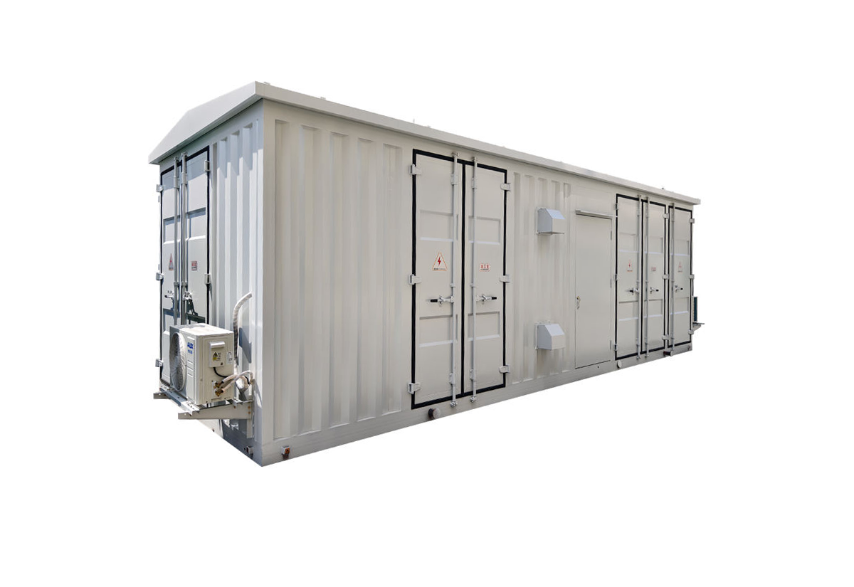
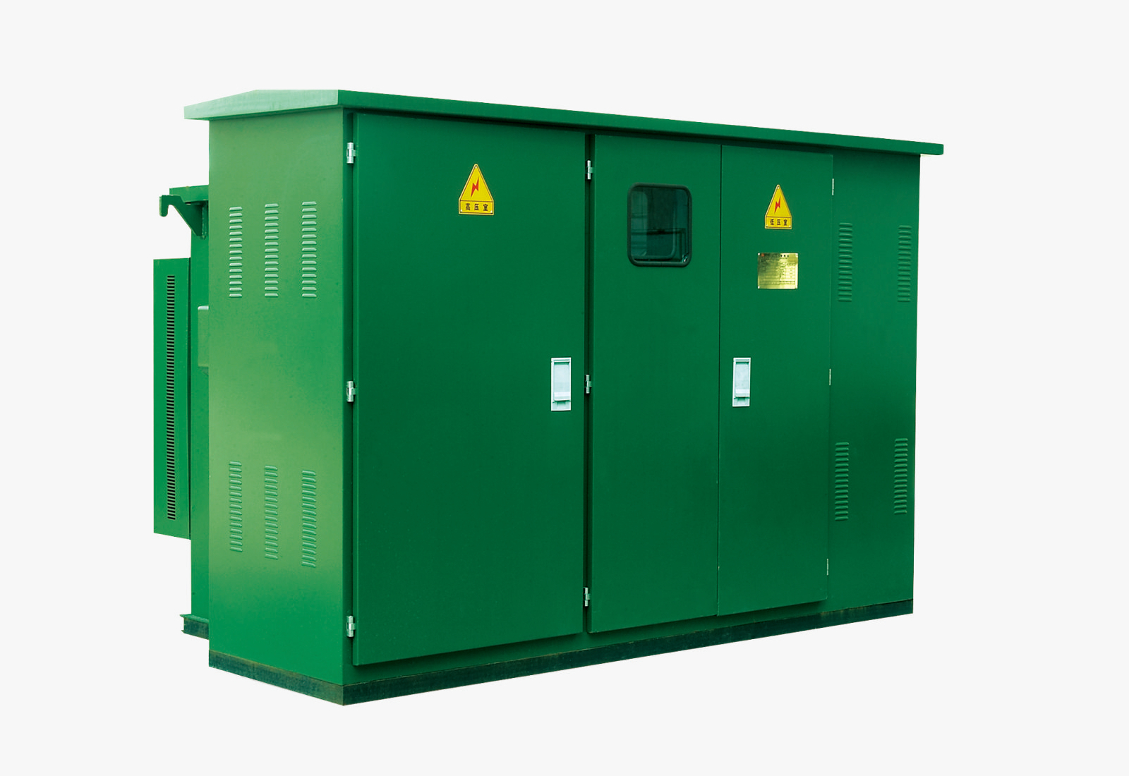
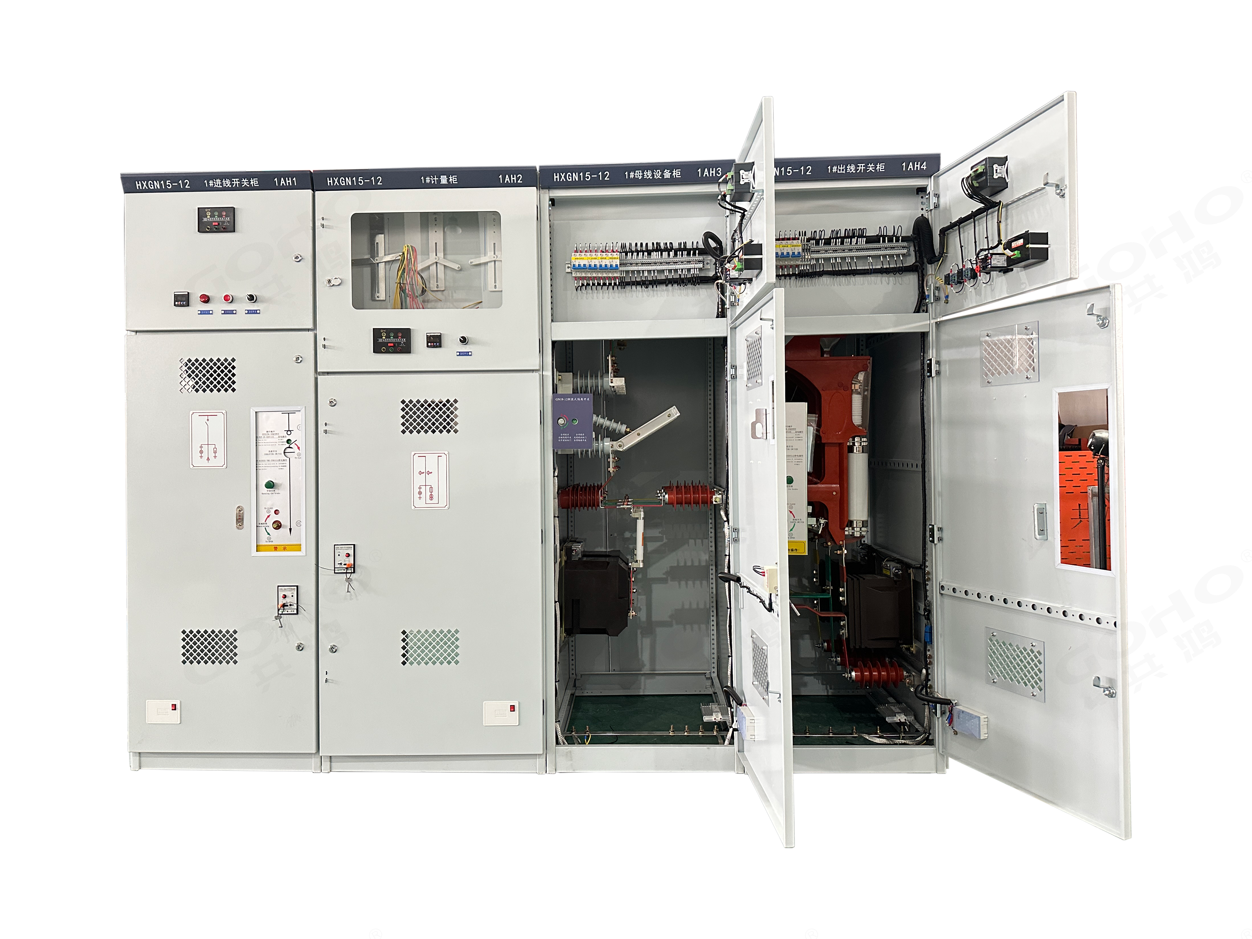
The GOHO ZFS YB□-40.5/0.69-1600 is a combined prefabricated substation specially designed for wind power and photovoltaic power generation systems. Rated at 40.5kV / 0.69kV, it integrates high-voltage switchgear, a step-up transformer, low-voltage distribution equipment, and a comprehensive monitoring system into a single weatherproof container-type enclosure — providing a complete plug-and-play power collection and grid-connection solution for large-scale renewable energy projects.
The step-up transformer converts inverter output voltage (690V) directly to medium voltage (40.5kV) for connection to the collector network, dramatically reducing transmission losses. Compared to 690V collection over the same distance, I²R losses are typically reduced by over 95% — a critical efficiency gain that directly improves project LCOE and ROI.
The integrated monitoring system features complete protection, measurement, control, and signal loops with fiber-optic communication for EMI-immune data transmission. LV measurement and control units are specially adapted to the low-temperature and high-humidity condensation environments common in wind and solar farms. The system supports IEC 61850, Modbus RTU/TCP, and DNP3 protocols for seamless integration with plant-level SCADA, enabling full "four-remote" operation and truly unmanned substations.
- 40.5kV / 0.69kV voltage ratio — matched to standard inverter output
- 1000kVA to 5000kVA capacity range — fully customizable per project
- Amorphous alloy core: 50–70% lower no-load loss vs CRGO steel
- S20 ultra-low-loss transformer option also available
- HV: SF6 LBS + fuse or vacuum breaker (up to 1250A)
- LV: MCCB or ACB incoming — up to 3200A
- Fiber-optic IEC 61850 monitoring — complete electrical & non-electrical telemetry
- Anti-condensation design with conformal-coated PCBs for harsh environments
- IP44 / IP54 weatherproof steel enclosure with anti-UV coating
- Grid-code compliant: LVRT, reactive power, anti-islanding, power quality
ZFS Wind & Solar Substation Specs
Complete technical parameters for the wind & solar combined prefabricated step-up substation.
| Model | YB□-40.5/0.69-1600 — Wind & Solar Combined Type |
|---|---|
| Rated Voltage (HV Side) | 40.5kV (35kV class) |
| Rated Voltage (LV Side) | 0.69kV (690V) — compatible with inverter output |
| Rated Capacity Range | 1000kVA – 5000kVA (customizable per project) |
| Rated Frequency | 50Hz / 60Hz |
| Transformer Type | Oil-immersed, ONAN self-cooling — Amorphous alloy or S20 low-loss series |
| No-Load Loss (Amorphous) | 50–70% lower than conventional CRGO silicon steel transformers |
| HV Protection | SF6 load break switch + current-limiting fuse / Vacuum circuit breaker (up to 1250A) |
| LV Incoming | Main MCCB or ACB — up to 3200A, inverter-compatible |
| Monitoring Interface | Integrated measurement & control unit with fiber optic communication |
| Communication Protocols | IEC 61850 / Modbus RTU / Modbus TCP / DNP3 (configurable) |
| Collected Parameters | V, I, P, Q, PF, f, THD + oil temp, winding temp, cabinet temp/humidity, door status, fire alarm |
| Enclosure Type | Container-type weatherproof steel enclosure |
| Enclosure Material | Heavy-duty steel plate with anti-corrosion & anti-UV coating |
| Degree of Protection | IP44 / IP54 (configurable) |
| Ambient Temperature | -25°C ~ +40°C (low-temperature option: -40°C) |
| Cooling Method | ONAN (Oil Natural Air Natural) + forced ventilation option |
| Grid Code Compliance | LVRT, reactive power compensation, power quality, anti-islanding protection |
| Automation Level | Four-remote (遥测/遥信/遥控/遥调) — unmanned operation capable |
| Installation Type | Skid-mounted container — outdoor ground-level installation |
| Applicable Standards | IEC 62271-202, GB/T 17467 |
Built for the Demands of Renewable Energy
Purpose-designed features that maximize energy harvest, minimize losses, and ensure reliable operation in the harshest environments.
Renewable Energy Optimized
Purpose-built for wind and solar with 40.5kV/0.69kV ratio — matches standard inverter output and MV collection network, no intermediate transformation needed.
Ultra-Low Loss Core
Amorphous alloy core cuts no-load loss by 50–70% vs CRGO steel. Maximizes energy harvest and dramatically improves project ROI over 20+ year life.
IEC 61850 Automation
Full substation automation with IEC 61850 protocol support. Four-remote functions enable seamless SCADA integration and fully unmanned operation.
Fiber Optic Communication
All monitoring data travels via fiber optic cable — complete electrical isolation, zero EMI interference, and reliable long-distance transmission.
Harsh Environment Ready
Conformal-coated PCBs and anti-condensation design handle high humidity, wide temperature swings, and corrosive atmospheres in desert, coastal, and high-altitude sites.
Comprehensive Monitoring
Collects all electrical parameters (V, I, P, Q, PF, f, THD) and non-electrical data (oil temp, winding temp, humidity, door status, fire alarm) for full condition awareness.
Container-Type Enclosure
Standardized container design enables cost-effective transport, rapid on-site installation, and easy relocation. Factory-assembled and fully tested.
Grid Code Compliant
Designed to meet grid connection requirements — LVRT, reactive power compensation, power quality, and anti-islanding protection per national grid codes.
Low-Temperature Option
Optional -40°C low-temperature rating for extreme cold climate installations. Heaters and cold-start components ensure reliable winter operation.
Where ZFS Excels
The preferred step-up substation for utility-scale renewable energy and distributed power projects.
Utility-Scale Solar Farms
Centralized PV power plants 10MW+
Onshore Wind Farms
Wind turbine step-up & collection
Offshore Wind Platforms
Offshore wind farm substations
Wind-Solar Hybrid
Hybrid renewable energy power plants
Energy Storage (ESS)
Battery storage grid connection
Microgrids & DER
Distributed energy & remote microgrids
Industrial CHP
Combined heat & power systems
Remote Electrification
Off-grid & remote area power
Certified for Global Renewable Projects
Manufactured and tested in compliance with international standards for substation and renewable energy equipment.
61850
Frequently Asked Questions
Common questions about wind & solar prefabricated substations. Have a specific project? Our engineering team can help.
Standard prefabricated substations (like our YBM or ZBW series) are designed for general power distribution — typically stepping down from medium voltage to low voltage for building or industrial use. The ZFS wind & solar substation is the opposite: it steps UP from inverter-level voltage (690V) to medium voltage (40.5kV) for collection and grid connection in renewable energy plants. Beyond the voltage ratio, it includes specialized features: 690V LV side matched to PV inverter or wind turbine output, amorphous alloy ultra-low-loss core optimized for variable-load operation, fiber-optic monitoring with IEC 61850 protocol support, conformal-coated electronics for harsh outdoor environments, anti-islanding and LVRT features for grid-code compliance, and a containerized design optimized for transport to remote sites. It's essentially a completely different product category purpose-built for renewable energy applications.
Amorphous alloy transformers reduce no-load (core) losses by 50–70% compared to conventional CRGO silicon steel transformers. For solar and wind applications, this is particularly impactful because the transformer is energized 24/7 but the renewable generator only produces power part of the time — at night or when the wind isn't blowing, you're still paying for no-load losses. Over a 25-year project lifespan, the cumulative energy savings from amorphous alloy cores can be substantial. As a rough example, for a 2500kVA substation in a utility solar farm, the amorphous alloy option might save approximately 15,000–25,000 kWh per year in no-load losses alone, which over 25 years adds up to significant revenue. The payback period for the premium is typically 3–7 years depending on electricity tariffs. We can provide a detailed lifecycle cost analysis for your specific project parameters.
The monitoring system uses dedicated measurement and control units installed in the LV compartment that collect all critical electrical and non-electrical parameters from the substation. Instead of using copper cables (which can pick up electromagnetic interference from the HV equipment), all data is transmitted via fiber optic cables to the station-level controller or directly to the SCADA system. This provides complete electrical isolation between the LV monitoring circuits and the communication network, eliminates EMI issues common in high-voltage environments, and enables reliable data transmission over long distances (kilometers if needed). The system supports standard protocols including IEC 61850 for substation automation, Modbus RTU/TCP for general SCADA integration, and DNP3 for utility-grade communication. It monitors: three-phase voltage, current, active/reactive power, power factor, frequency, harmonic distortion (THD), transformer top-oil temperature, winding hot-spot temperature, cabinet internal temperature and humidity, door position status, and fire alarm status.
Yes, the ZFS series is specifically designed for harsh outdoor environments. Key features for extreme conditions include: heavy-duty steel enclosure with anti-corrosion and anti-UV coating for long-term durability; IP54 protection rating option for dust-tight and splash-proof performance; conformal-coated (lacquered) printed circuit boards in all LV measurement and control units, providing a protective layer against moisture, salt, and corrosive atmospheres; built-in anti-condensation system with heaters and ventilation to prevent moisture buildup when temperature swings are large (common in deserts — hot days, cold nights); optional low-temperature rating down to -40°C for cold climate installations; and the fiber-optic communication system is inherently immune to the EMI and lightning-induced surges common in open desert and coastal sites. For particularly aggressive environments (heavy salt spray, high sand abrasion, extreme pollution), we can provide upgraded enclosure materials and additional protection measures.
The ZFS substation is designed to support the grid code requirements typically mandated for renewable energy grid connection. While the specific requirements vary by country and grid operator, our substation supports: low-voltage ride-through (LVRT) capability — the ability to stay connected during voltage dips and support grid recovery; reactive power compensation and power factor control for voltage regulation; harmonic monitoring and management to ensure power quality compliance; anti-islanding protection to detect islanded operation and disconnect as required by grid codes; and frequency response and active power control features. The monitoring system provides the measurement and control infrastructure needed to implement these functions. For specific grid code requirements (e.g., GB/T 19964, IEC 61400-21, IEEE 1547, or local utility standards), please let us know which code applies to your project and we'll configure the protection and control system accordingly.
One of the biggest advantages of the containerized prefabricated substation is rapid deployment. The unit arrives at site fully assembled, wired, and factory-tested. On-site requirements include: a prepared foundation (concrete pad or load-bearing gravel base — we provide foundation drawings), crane or lifting equipment to position the unit, HV cable connections to the collection network, LV cable connections from inverters or wind turbines, ground/earthing connections, fiber optic or communication cable connections, and commissioning testing. Total on-site time is typically 3–10 days per unit, compared to several weeks or months for a traditional built-up substation building. For large solar farms with multiple units, installation can be staged and parallelized. We also offer on-site commissioning support, including insulation tests, protection relay settings verification, SCADA communication testing, and energization supervision. Our team can also provide training for your operations and maintenance staff.
Design Your Renewable Substation
Send us your plant layout and inverter/WTG specifications. Get a custom step-up substation with detailed loss analysis and grid-code compliance review.
Get a Project Quote