
DZ47
Miniature Circuit Breaker
GOHO® builds the DZ47‑63 miniature circuit breaker for final circuit protection in distribution boards and machine enclosures. It covers 6 A to 63 A at 230 V in single‑pole and 400 V in multi‑pole versions, with a breaking capacity of 4500 or 6000 A and a choice of B, C or D tripping characteristic. The case is a flame‑retardant moulding on a standard 35 mm DIN rail, and the trip assembly combines a bimetal strip for overload with an electromagnetic release for short circuit. It is the last device in the chain that starts with the GHW3 air circuit breaker at the incomer and passes through the GHM3 moulded case breaker at the sub‑main.

- Rated Operational Voltage
- 230 V / 400 V Single pole 230 V; two, three and four pole 400 V
- Rated Current
- 6 · 10 · 16 · 20 · 25 · 32 · 40 · 50 · 63 A B, C and D tripping curves
- Breaking Capacity
- 4500 / 6000 A Icn at 230 / 400 V, 50 / 60 Hz
Technical Specifications
The DZ47‑63 is a single family: one case width per pole, one rail mounting, and the rating and the curve set by the bimetal and the magnetic release inside. The table below is the standard platform.
| Parameter | Value |
|---|---|
| Model | DZ47-63 |
| Rated operational voltage Un | AC 230 V (1-pole) / AC 400 V (2, 3 and 4-pole) |
| Rated frequency | 50 / 60 Hz |
| Number of poles | 1P, 1P+N, 2P, 3P, 3P+N, 4P |
| Rated current In | 6 · 10 · 16 · 20 · 25 · 32 · 40 · 50 · 63 A |
| Rated short-circuit breaking capacity Icn | 4500 / 6000 A |
| Rated insulation voltage Ui | 500 V |
| Rated impulse withstand voltage Uimp | 4 kV |
| Dielectric test voltage, 1 min, at industrial frequency | 2 kV |
| Tripping characteristic | B (3 – 5 In) / C (5 – 10 In) / D (10 – 16 In) |
| Release type | Thermo-magnetic: bimetal strip for overload, electromagnetic release for short circuit |
| Reference temperature for thermal calibration | +30 °C |
| Short-circuit test | Calibrated at 30 °C |
| Terminal capacity | 25 mm² cable (AWG 18 – 3), tightening torque 2 N·m |
| Mounting | 35 mm DIN rail to EN 60715, fast clip device |
| Connection | Top and bottom; cable or pin-type busbar comb |
| Front-face protection | IP20 |
| Pollution degree | 2 |
| Mechanical endurance | ≥ 20 000 operating cycles |
| Electrical endurance | ≥ 6000 operating cycles |
| Contact position indication | Visible indicator window on the front face |
| Ambient temperature | −5 °C to +40 °C (storage −25 °C to +70 °C) |
| Product standard | GB/T 10963.1 · IEC 60898-1 |
Values above describe the standard DZ47‑63 platform and are given as typical ratings. The rated current and the tripping characteristic of a specific breaker follow the order code. Breaking capacity options and degrees of protection for specific installations are confirmed on the datasheet issued with the quotation.
Tripping Characteristics
The curve is what decides whether the breaker trips on the inrush current of the load it protects. Choosing the wrong curve is the most common cause of nuisance tripping on a circuit that is otherwise correctly rated.
| Characteristic | B curve | C curve | D curve |
|---|---|---|---|
| Instantaneous tripping range | 3 – 5 In | 5 – 10 In | 10 – 16 In |
| Overload range, 1.13 In | No trip within 1 hour | No trip within 1 hour | No trip within 1 hour |
| Overload range, 1.45 In | Trip within 1 hour | Trip within 1 hour | Trip within 1 hour |
| Typical load | Long cable runs in TN and IT systems; resistive loads with negligible inrush | Resistive and inductive loads with low inrush — the general-purpose choice | LV/LV transformers, motors and lamps with high closing inrush |
The C curve is the correct default for general distribution. The B curve is used where a long cable run has to be protected against a modest overload, and the D curve only where the closing inrush of the load genuinely exceeds the C curve, because a D curve breaker gives less protection against a low-level fault on the same circuit.
Service Conditions
A miniature breaker works in a distribution board in a wall or a machine enclosure. The ambient temperature around the board, the humidity and the pollution of the room set the working limits.
| Condition | Limits for standard supply |
|---|---|
| Ambient temperature | −5 °C to +40 °C |
| Average ambient temperature over 24 hours | ≤ +35 °C |
| Storage temperature | −25 °C to +70 °C |
| Altitude | ≤ 2000 m |
| Relative humidity | ≤ 95 % at +25 °C; tropical treatment to 95 % at +55 °C on request |
| Pollution degree | 2 |
| Front-face protection | IP20 |
| Mounting | 35 mm DIN rail to EN 60715, inside a distribution board or enclosure |
| Installation | Indoor, in a dry position; no explosive or corrosive atmosphere, no conductive dust |
The thermal calibration refers to +30 °C, so a breaker in a warm plant room carries slightly less than its rated current and one in a cold room slightly more. Where the ambient temperature inside the board is far from +30 °C, a correction is applied to the rating rather than leaving the nominal figure to be read as a working value.
Construction & Operating Principle
Housing and mechanism
The case is a high flame‑retardant, high‑strength engineering plastic moulding, and the moving parts of the mechanism are plastic too. Using moulded parts rather than metal in the mechanism keeps the moment of inertia low, so the toggle reaches the latch quickly after a fault is detected. The result is the short total operating time that a modern miniature breaker depends on. The case is sealed in service and the contacts cannot be inspected or replaced: when the breaker reaches the end of its electrical life it is replaced, not repaired.
Contact system and arc quenching
The contact system is current limiting: as the contacts separate under a fault, the electrodynamic force between them pushes them further apart, so the arc is drawn and extinguished quickly and the peak let‑through current is reduced. The arc is driven magnetically into a quenching chamber to be cooled and split. That combination is what allows a breaker only one module wide to reach a breaking capacity of 4500 or 6000 A.
Trip assembly
Overload protection comes from a bimetal strip carrying the circuit current. The strip bends as it heats, and above about 1.13 times the rated current it eventually reaches the latch; the higher the current, the faster it gets there. That is the inverse‑time characteristic described in the table above. Short‑circuit protection comes from a separate electromagnetic release that operates immediately once the current reaches the multiple of In fixed by the curve. Because the two elements are independent, the breaker protects both against a gradual overload and against a fault.
What the breaker does not do
A DZ47 is an overcurrent device. It is not a residual current device, so it does not protect a person against electric shock and it does not detect an earth‑leakage fault on its own. Where that protection is required, an RCD or an RCBO is used, and the DZ47 sits behind it as the overcurrent device. It is also not a switch‑disconnector for isolation purposes beyond the occasional operation for which it is rated: for a circuit that has to be isolated regularly, a proper switch‑disconnector or an isolation device is used.
Poles, Curves & Selecting The Right Rating
Choosing the pole version
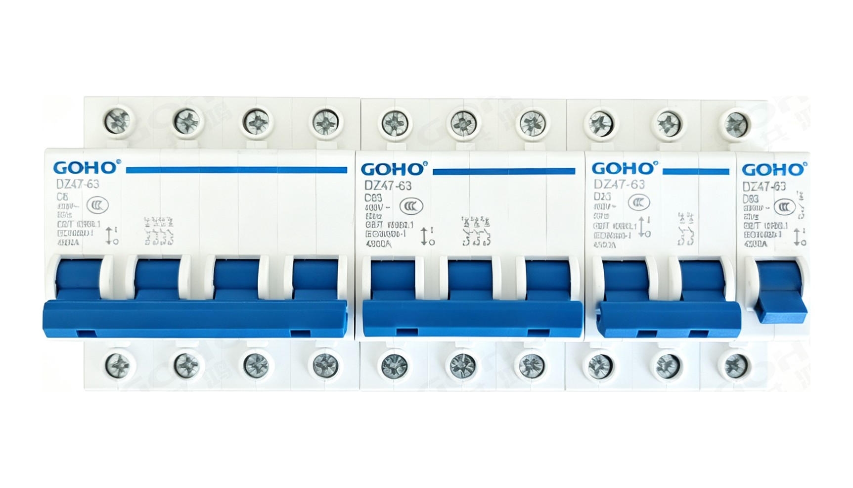
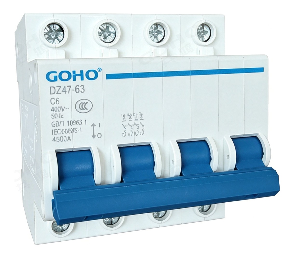
A 1P breaker protects a single‑phase circuit and switches only the phase, so the neutral stays solid and the circuit is not fully isolated. A 1P+N switches the neutral as well, which is what a single‑phase circuit needs where the neutral has to be broken for maintenance. A 2P protects a single‑phase circuit in a system where both conductors are live to earth, or a DC circuit. A 3P protects a three‑phase circuit without neutral and a 4P or 3P+N protects one with a neutral that has to be switched.
Choosing the curve
The C curve is the general‑purpose choice for distribution: it tolerates the modest inrush of a fluorescent lighting circuit or a small motor while still tripping quickly on a fault. The B curve is used where a long cable run makes a low‑level earth fault likely and the circuit has to be cleared quickly, and where the load has almost no inrush. The D curve is reserved for loads with a genuinely high inrush —a small transformer energised from the board, a large motor, or a group of lamps —because it gives up sensitivity at the bottom of its magnetic range to get there.
Choosing the rating
The rating is chosen so that the circuit's design current is at or below the breaker rating and the breaker rating is at or below the current‑carrying capacity of the cable. Both halves matter: a breaker rated above the cable capacity protects the load but leaves the cable able to overheat, and one rated below the design current trips in normal service. The breaking capacity then has to exceed the prospective short‑circuit current at the point where the breaker is fitted.
Grading through the installation
The miniature breaker is the bottom of the chain. The GHM3 moulded case breaker above it is set to trip more slowly at the current levels where the DZ47 operates, so a fault on a single final circuit trips only that circuit. The GHW3 air circuit breaker at the incomer holds the fault for the short‑time delay while the two below it clear their own zones. Selecting the three families together, with their settings calculated as a set, is what produces a board where a fault on one socket does not darken the building.
Ratings & Options
Four groups of ratings cover almost every final circuit and small sub‑main in a normal installation, and the pole version and curve are chosen separately from the rating.
The usual ratings for lighting circuits and for socket outlets, where the circuit current is low and the load has little or no inrush. C curve as standard, B curve where a long cable run has to be protected.
Larger socket circuits, small motors and air‑conditioning or water‑heating loads. C curve normally, D curve where the motor starting current or the transformer inrush would otherwise trip the breaker.
The largest ratings in the family, used for a small sub‑main or a large single load. Above this level a GHM3 moulded case breaker takes over, because the miniature family stops at 63 A.
Versions with a switched neutral for circuits that have to be fully isolated for maintenance, and for systems where the neutral is not solidly earthed. Same case width per pole, same rail, same accessories.
| Option | Available |
|---|---|
| Model | DZ47-63 |
| Poles | 1P, 1P+N, 2P, 3P, 3P+N, 4P |
| Rated current | 6 / 10 / 16 / 20 / 25 / 32 / 40 / 50 / 63 A |
| Tripping characteristic | B (3 – 5 In), C (5 – 10 In), D (10 – 16 In) |
| Breaking capacity Icn | 4500 A or 6000 A |
| Rated voltage | 230 V single pole; 400 V two, three and four pole |
| Mounting | 35 mm DIN rail to EN 60715 |
| Connection | Cable up to 25 mm², or pin-type busbar comb |
| Accessories | Auxiliary contact, alarm contact and shunt release are available as add-on modules on the appropriate versions |
| Enclosure | Distribution boards and consumer units to suit the pole count |
The order code combines the model, the pole count, the curve and the rating, for example DZ47-63, 1 pole, C curve, 20 A. Quoting against that form avoids the most common error in ordering miniature breakers, which is a correct rating supplied on the wrong curve.
Key Features
Applications
The DZ47 is used wherever a final circuit or a small sub‑main has to be protected against overload and short circuit — which in practice means every distribution board in a building and most machine panels.
- Domestic consumer units — lighting, socket and appliance circuits
- Apartment, hotel and dormitory distribution boards
- Office lighting and power circuits, per zone or per floor
- Commercial boards in shops, restaurants and small businesses
- Schools, clinics and public buildings — final circuit protection
- Machine control panels — control, auxiliary and heater circuits
- Small sub-mains up to 63 A in a larger board
- Telecom and data cabinets — equipment and auxiliary circuit protection
- Pumping, irrigation and agricultural installations — small motor circuits
- Workshops and small production units — machine and lighting circuits
- Temporary site distribution boards and site cabins
- Renovation and retrofit — replacing miniature breakers in an existing DIN rail board
What We Need to Quote Your Breaker
The rating, the pole version and the curve are all needed together — a correct rating on the wrong curve is the most common ordering error. With the items below we can return a firm quotation.
- Circuit current and the required rated current In
- System voltage and whether the circuit is single-phase or three-phase
- Pole version required — 1P, 1P+N, 2P, 3P, 3P+N or 4P
- Whether the neutral has to be switched
- Tripping characteristic required — B, C or D, and the load type it protects
- Prospective short-circuit current at the board, to set the breaking capacity
- Cable size, so that the breaker rating can be checked against the cable capacity
- Quantity, destination and whether add-on accessories are required
Send these to gohointl@gmail.com and we will reply with a priced offer, the curve and rating confirmation, and the routine test plan for the breakers.
Standards & Documentation
| Item | Reference |
|---|---|
| Product standard, China | GB/T 10963.1 — Electrical accessories, circuit-breakers for overcurrent protection for household and similar installations |
| Product standard, international | IEC 60898-1 — Electrical accessories, circuit-breakers for overcurrent protection for household and similar installations |
| Contact position indication | Visible indicator window on the front face |
| Routine test, main circuit | Main circuit resistance measurement and power-frequency withstand test |
| Routine test, calibration | Calibration check of the thermal release and the magnetic release against the ordered curve |
| Routine test, mechanical | Full open / close operating sequence and handle and clip check |
| Documentation supplied | Rating and curve confirmation, routine test record and operating instructions; declaration of conformity supplied with the shipment |
Type test reports for the DZ47‑63 platform and the routine test record for the individual breaker are available for project qualification on request.
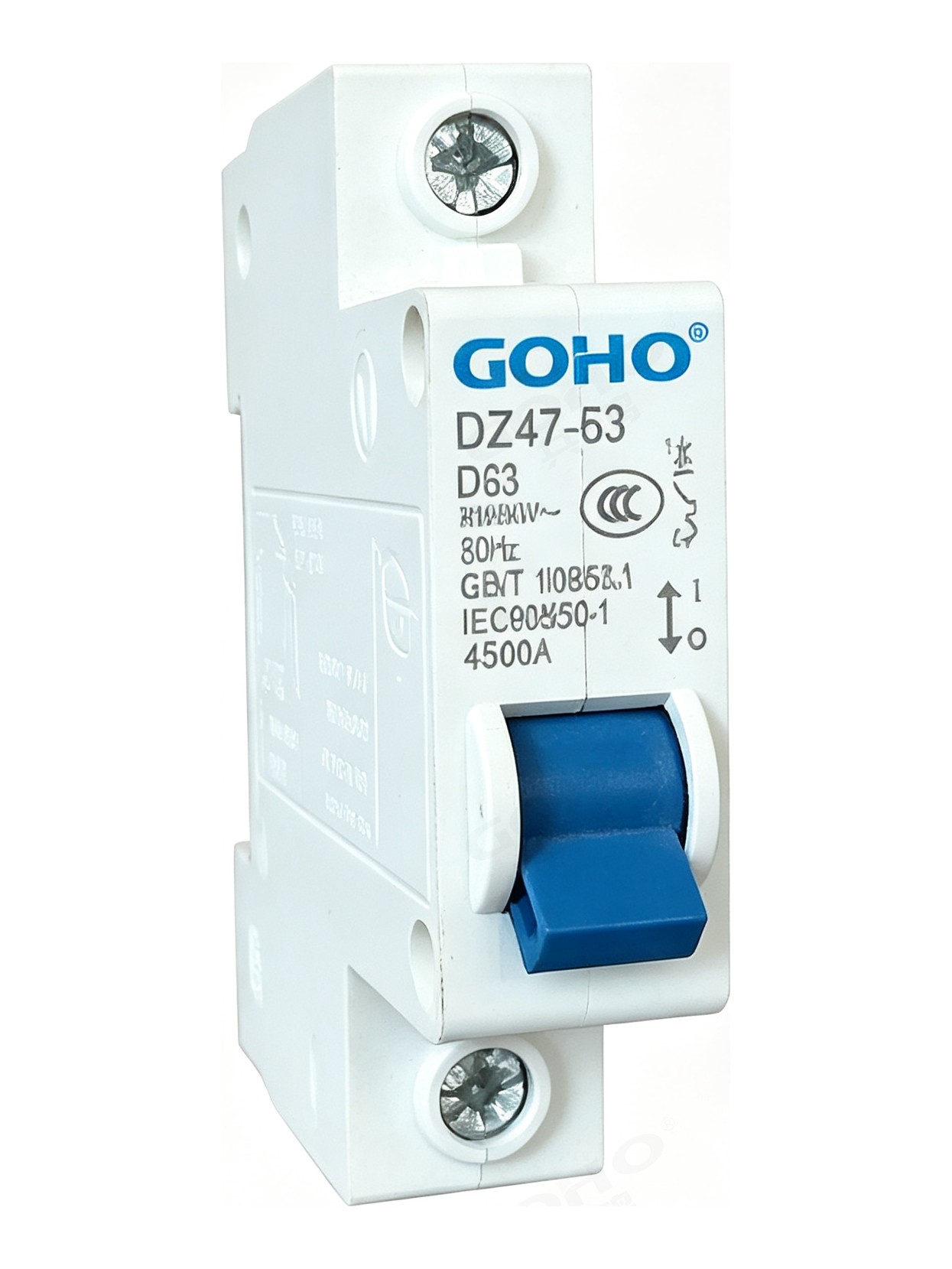
Breakers are assembled in our own factory in Yueqing, Zhejiang — the same site that builds our switchgear, transformers and prefabricated substations. Case assembly, release fitting and calibration, and routine testing all happen in‑house, which keeps both the delivery schedule and the quality check inside our control.
GOHO® is a registered trademark of Gonghong Electric Appliance Co., Ltd. Technical data describes the standard DZ47‑63 miniature circuit breaker platform and is given as typical ratings; the ratings of a specific unit follow the approved drawing and the configuration ordered. Ratings outside the table in this page, and site conditions outside the stated limits, are quoted on application. Product images are shown for illustration. Please refer to the drawing issued with your offer for dimensional and foundation data.