
SIVACON 8PT
Low Voltage Switchgear
GOHO® builds and exports the SIVACON 8PT low‑voltage switchgear assembly under license from Siemens Ltd., China. It is a modular, type‑tested system of compartmented functional units — incoming and outgoing feeders, bus couplers, motor starters and power factor correction — engineered to your single‑line diagram.
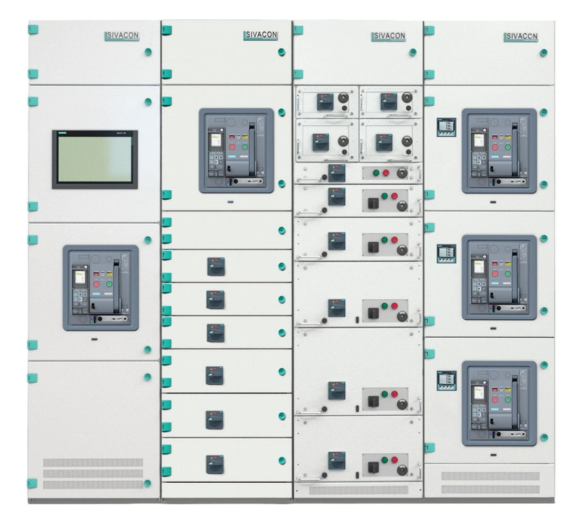
- Horizontal Busbar
- Up to 7400 A Single, three-ply or double three-ply system
- Internal Separation
- Up to Form 4b To IEC 61439-2, up to category 7
- Degree of Protection
- IP30 – IP54 Indoor installation, IR 3
Technical Specifications
| Item | Specification |
|---|---|
| Standards | IEC 61439-1 & IEC 61439-2; internal arc tested to IEC TR 61641; degree of protection to IEC 60529 |
| Application | Power distribution and motor control (MCC) |
| Rated insulation voltage (Ui) | 690 V / 1000 V |
| Rated operational voltage (Ue) | Up to 690 V AC (50 / 60 Hz) |
| Rated impulse withstand voltage (Uimp) | 8 kV / 12 kV |
| Overvoltage category | III / IV |
| Rated current of horizontal busbar (In) | Up to 7400 A |
| Rated short-time withstand current (Icw) | Up to 150 kA / 1 s |
| Rated peak withstand current (Ipk) | Up to 375 kA |
| Rated conditional short-circuit current (Icc) | 100 kA |
| Internal arc fault | 50 kA / 0.3 s at 690 V; 100 kA / 0.5 s at 415 V |
| Internal separation | Up to Form 4b to IEC 61439-2 (up to category 7, each functional unit with its own connection box) |
| Degree of protection | IP30, IP31, IP40, IP41, IP42 (ventilated) · IP40, IP54 (non-ventilated) |
| Earthing system | TT / IT / TNS / TNC |
| Communication | Profibus, Profinet, Modbus |
| Surface finish | Galvanized / Aluzinc / powder coated / painted |
| Application environment | Indoor, IR 3 |
* Ratings above describe the licensed SIVACON 8PT platform. The final rating of each project follows the approved single‑line diagram and the selected protective devices. Contact us for the type‑test documentation relevant to your specification.
Frame, Enclosure & Busbar System
| Item | Specification |
|---|---|
| Frame construction | Screwed or welded steel profile; 25 mm modular hole pitch for later extension |
| Sheet thickness | Frame 2.5 mm · enclosure 2.0 mm |
| Horizontal busbar position | Top of the cubicle, with arc barrier to limit internal arc faults |
| Single-ply busbar system | In ≤ 3200 A · cubicle 2200 × 600 / 800 / 1000 mm |
| Single three-ply busbar system | In ≤ 5000 A · cubicle 2200 × 800 / 1000 / 1200 mm |
| Double three-ply busbar system | In ≤ 7400 A · cubicle 2600 × 800 / 1000 / 1200 mm |
| Busbar short-circuit rating | Icw / Ipk up to 150 kA (1 s) / 375 kA |
| Busbar compartment | Segregated from the device compartment; coupled from the cubicle top |
| Door opening angle | Up to 180° single cubicle · more than 140° when coupled |
| Cubicle dimensions H × W × D (mm) | H 2200 / 2600 · W 400 / 600 / 800 / 1000 / 1200 · D 600 / 800 / 1000 / 1200 |
| Cable connection | Top or bottom entry; front or rear connection |
| Installation | Wall‑mounted or free‑standing |
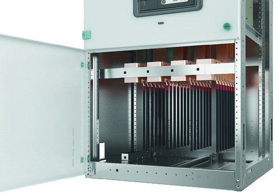
Design Variants
One cubicle platform covers the whole low‑voltage line‑up, so incomers, bus couplers, feeders, motor starters and compensation can be combined in a single continuous board.
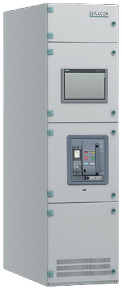
One air circuit‑breaker per cubicle — high‑current incoming and outgoing feeders.
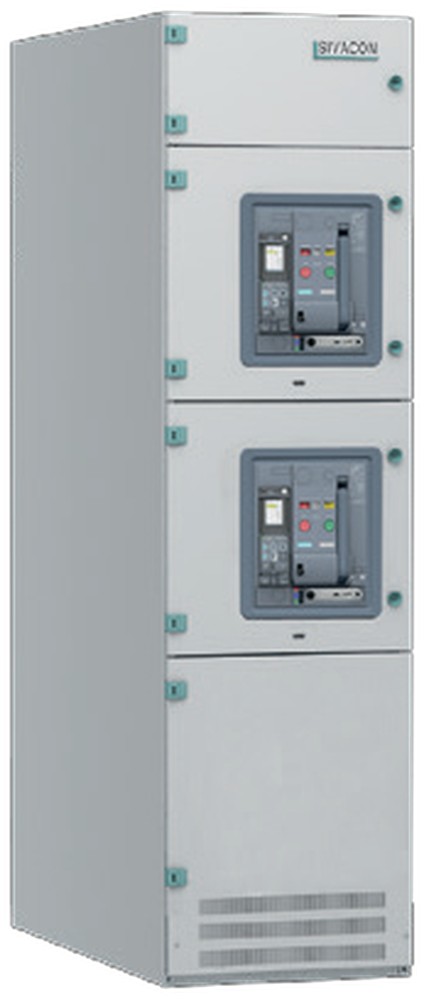
Two air circuit‑breakers per cubicle; the upper device can serve as a bus coupler.
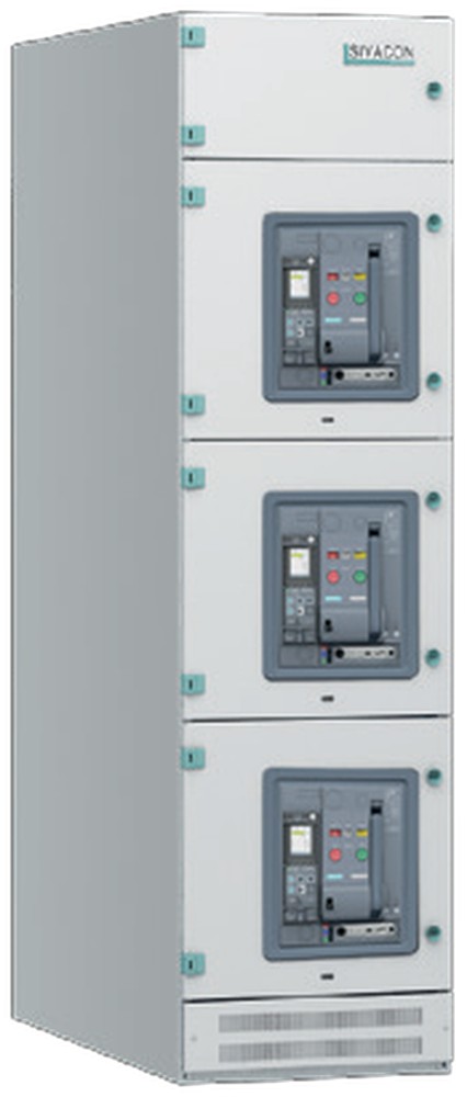
Three air circuit‑breakers per cubicle for incoming and outgoing feeders.
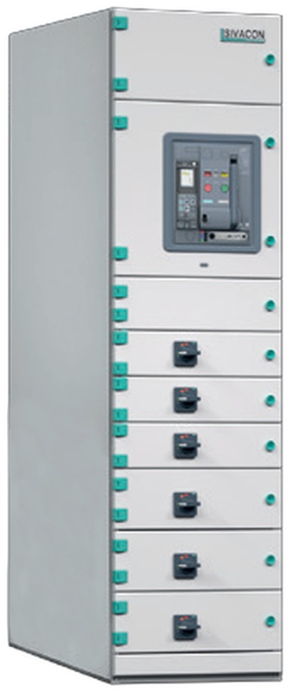
Fixed‑mounted cable feeder modules with moulded‑case devices, separation 3b / 4b.
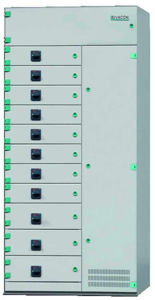
Fixed‑mounted cubicle mixing air and moulded‑case circuit‑breakers in one 600 mm width.
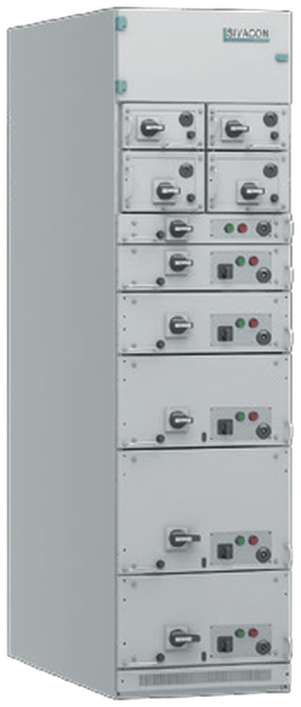
Withdrawable functional units, including ½ modules, for cable feeders and motor starters.
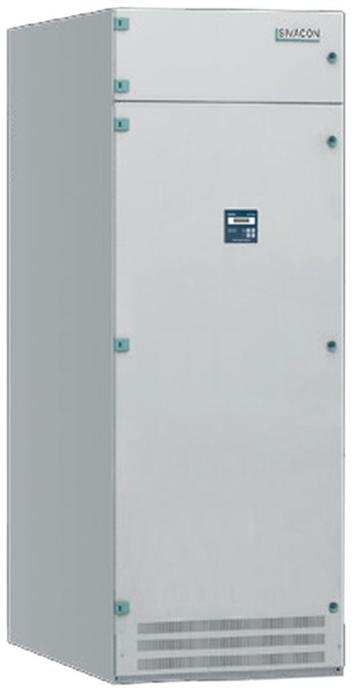
Power factor correction, non‑detuned up to 500 kvar or detuned up to 350 kvar.
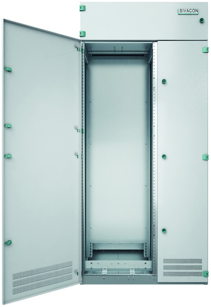
Customer‑designed cubicle for free arrangement of devices, Icw up to 65 kA.
| Variant | Typical Application | Cable Entry | Separation |
|---|---|---|---|
| FCB1 | Main incomer, large outgoing feeder | Front or rear / top or bottom | Device, busbar and cable compartments separate |
| FCB2 / FCB2BC | Double feeder cubicle, bus coupler | Front or rear | Independent device compartments |
| FCB3 | Multiple outgoing feeders | Front or rear | Independent device compartments |
| OFF3 / OFF6 | Distribution with high supply continuity | Rear (OFF6 also side) | Form 3b / 4b, each device with own door |
| OFW | MCC and mixed cable feeders | Front (400 mm) or rear (600 mm) cable compartment | Draw‑out units, IP20B when withdrawn |
| PFC / CCS | Compensation / free design | To project | Per project requirement |
Key Features
Cabinet Construction & Safety
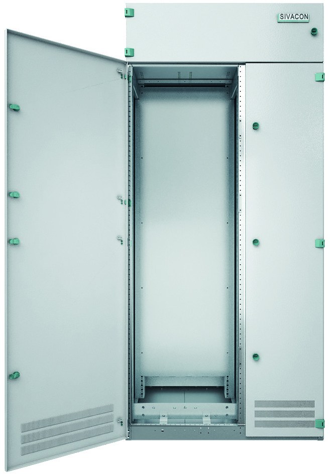
Two details decide how a low‑voltage board behaves on a bad day: how far one fault can spread inside the enclosure, and where the energy goes if an arc occurs. Both are designed in, not added later.
Applications
- Data centres — main low‑voltage distribution and UPS bypass feeders, where compartmentation keeps a single fault from taking the board down.
- Commercial buildings and high‑rise risers — floor distribution boards fed from a central 8PT incomer and bus coupler.
- Solar PV plants — inverter output collection and step‑up distribution, including plant auxiliary supply.
- Wind farms — turbine‑side auxiliary supply and collector‑system distribution.
- Metro, rail and airports — traction auxiliary power supply and infrastructure distribution where continuity matters.
- Cement, steel and heavy process plants — motor control centres with a high concentration of starter circuits.
- Oil, gas and petrochemical facilities — distribution in harsh environments, with arc‑tested enclosures.
- Paper mills and other continuous‑process industries — process lines where an unplanned shutdown is costly.
What We Need to Quote Your Line-Up
Because every SIVACON 8PT board is engineered to the project drawing, a few documents are enough for us to come back with a priced cubicle schedule.
- Single‑line diagram and cubicle schedule
- System voltage, frequency and earthing system
- Short‑circuit level (Icw / Ipk) at the board
- Busbar rating and cable entry direction
- Required internal separation form
- Degree of protection (indoor / outdoor duty)
- Circuit list with device ratings and duties
- Any metering, protection or communication requirement
Send these to gohointl@gmail.com and we will return a cubicle‑by‑cubicle quotation, including the type‑test documentation relevant to your specification.
License & Documentation
| Licensed Series | License No. | Issued By | Licensee |
|---|---|---|---|
| SIVACON 8PT | SIVACON 8PT/010726/HO/SH/CH | Siemens Ltd., China | Gonghong Electric Appliance Co., Ltd. |
License certificate and type‑test documentation are available on request for project qualification.
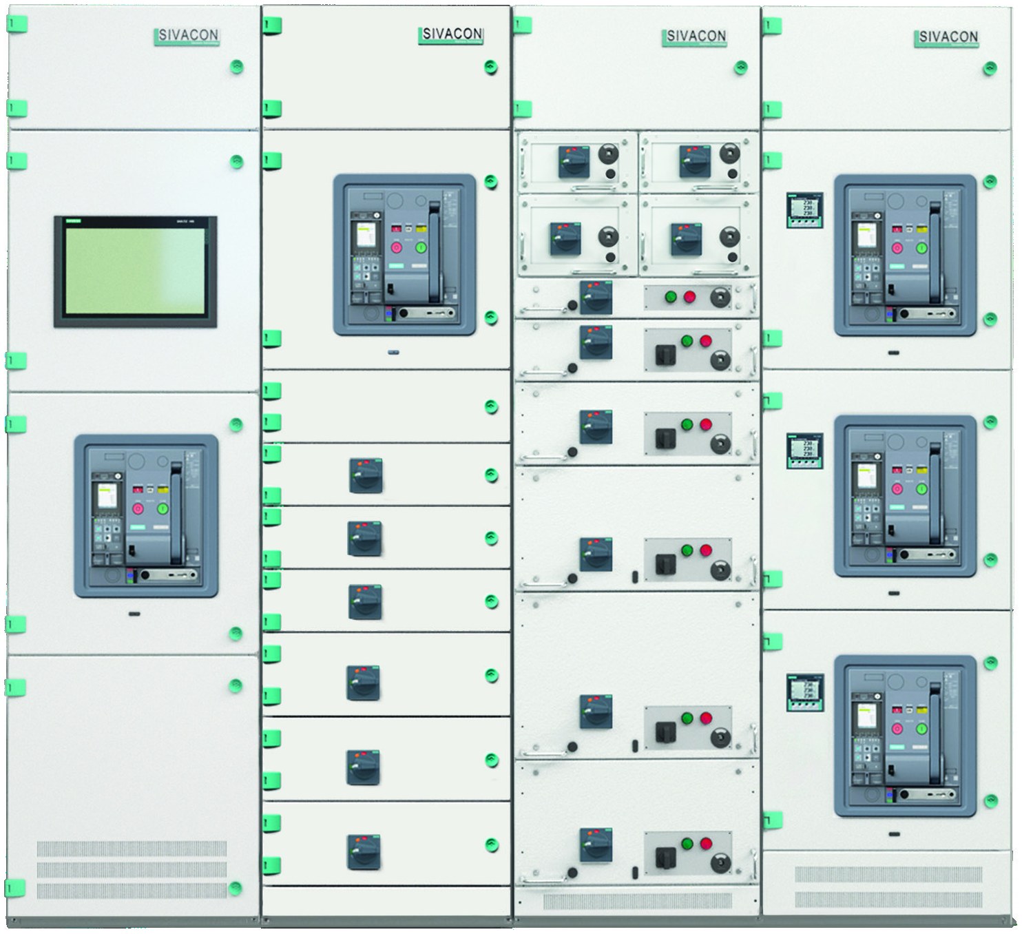
Every cubicle we ship is assembled in our own factory in Yueqing, Zhejiang — the same site that supplies our medium‑voltage switchgear, transformers and prefabricated substations. Sheet‑metal fabrication, busbar machining, assembly and routine testing all happen in‑house, which is what keeps the schedule and the quality check inside our control.
SIEMENS and SIVACON are registered trademarks of Siemens AG. GOHO® is a registered trademark of Gonghong Electric Appliance Co., Ltd. Gonghong Electric Appliance Co., Ltd. is an authorized licensee for the SIVACON 8PT low voltage assembly series. Technical data describes the licensed SIVACON 8PT platform; the rating of a specific board follows the approved project drawings and selected devices. Product images are shown for illustration.