
ZW8‑12
Pole Mounted Outdoor Vacuum Circuit Breaker
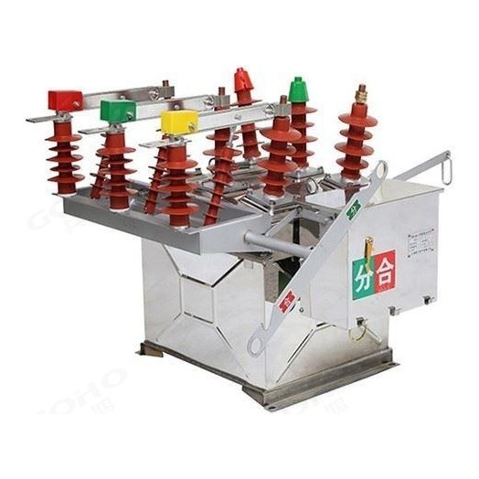
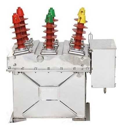
GOHO® builds the ZW8‑12 three‑pole outdoor vacuum circuit breaker for 12 kV overhead distribution lines. The three vacuum interrupters sit inside one steel tank with solid insulation between the phases, and the whole breaker is bolted to a steel frame on the pole with the mechanism and the control cabinet carried underneath. It switches load current, overload current and short‑circuit current on city and rural networks, and can be supplied as a combined breaker with an integral isolating switch so that a visible break is available on the line.
- Rated Voltage
- 12 kV Three-phase, 50 Hz, outdoor pole-mounted
- Rated Normal Current
- 630 A 1250 A available on the same frame
- Short-Circuit Breaking
- 12.5 · 16 · 20 kA Peak making 31.5 · 40 · 50 kA, 4 s duty
Technical Specifications
The ZW8‑12 is built on one tank and one frame across the whole rating range. What changes between ratings is the interrupter, the contact assembly and the mechanism spring.
| Parameter | Value |
|---|---|
| Rated voltage Ur | 12 kV |
| Highest voltage for equipment Um | 12 kV |
| Rated frequency | 50 Hz |
| Number of poles | 3 |
| Rated normal current Ir | 630 A (1250 A on request) |
| Rated short-circuit breaking current Isc | 12.5 / 16 / 20 kA |
| Rated short-circuit making current (peak) | 31.5 / 40 / 50 kA |
| Rated short-time withstand current Ik, 4 s | 12.5 / 16 / 20 kA |
| Rated peak withstand current Ip | 31.5 / 40 / 50 kA |
| Rated duration of short circuit | 4 s |
| Rated power-frequency withstand voltage, 1 min (dry) | 42 kV |
| Rated lightning impulse withstand voltage (peak) | 75 kV |
| Rated operating sequence | O – 0.3 s – CO – 180 s – CO |
| Rated short-circuit breaking operations | 20 |
| Contact gap | 11 ± 1 mm |
| Contact overtravel (contact spring compression) | 3 +1.0 / −0.3 mm |
| Three-phase opening / closing asynchronism | ≤ 2 ms |
| Contact bounce time on closing | ≤ 2 ms |
| Average opening speed | 1.0 ± 0.2 m/s |
| Average closing speed | 0.7 ± 0.15 m/s |
| Opening time | 15 – 60 ms |
| Closing time | 25 – 100 ms |
| Main circuit resistance per phase | ≤ 120 µΩ |
| Permissible contact wear (accumulated thickness) | 3 mm |
| Rated control and auxiliary circuit voltage | DC 110 V / 220 V |
| Enclosure protection, sealed version | IP65 |
| Mechanical endurance | 10 000 operating cycles |
| Product standard | GB/T 1984 · IEC 62271-100 |
Values above describe the standard ZW8‑12 platform and are given as typical ratings. The rating combination of a specific breaker follows the approved drawing, the interrupter fitted and the mechanism ordered. The sealed IP65 variant, the 1250 A rating and ratings with an integral isolating switch are quoted on application.
Service Conditions
The ZW8‑12 is mounted on a pole in the open. It has no kiosk and no canopy, so the site conditions below are part of the specification rather than a general note.
| Condition | Limits for standard supply |
|---|---|
| Ambient temperature | −30 °C to +40 °C |
| Altitude | ≤ 1000 m (higher on request) |
| Wind pressure | ≤ 700 Pa (equivalent to 34 m/s) |
| Air pollution level | Class IV |
| Ice coating thickness | ≤ 10 mm |
| Relative humidity, daily mean | ≤ 95 % |
| Seismic intensity | ≤ 8 degrees |
| Installation | Pole-mounted on a steel frame, at least 4 m above ground, on a single or double pole; mounted level and secure |
| Maintenance | Periodic minor inspection; the silica gel desiccant in the base is replaced when it turns light yellow |
Sites outside these limits — high altitude, heavier ice loading, a lower minimum temperature or a different pollution class — are handled by agreement at the enquiry stage, because the external insulation, the tank sealing and the mechanism heater are selected against them.
Construction & Operating Principle
Three-phase common tank
The three vacuum interrupters are housed in a single steel tank rather than in three separate columns. Phase-to-phase and phase-to-earth insulation inside the tank is provided by solid SMC insulating material, so the tank stays small and light and the breaker is easier to lift onto the pole than a three-column design of the same rating. The primary terminals are brought out through bushings on the tank walls.
Sealed, condensation-controlled enclosure
The tank is sealed against rain and dust, and a breather with a silica gel desiccant in the base keeps the internal air dry so that condensation does not form on the interrupters when the temperature drops overnight. The desiccant is the one consumable on the breaker: it is inspected at the periodic check and replaced when its colour turns light yellow. A fully sealed stainless tank rated IP65 is available for coastal, desert and heavily polluted sites.
Operating mechanism
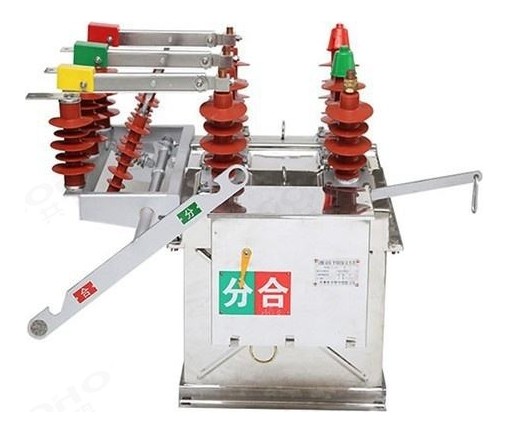
The mechanism is a CT23 spring stored-energy type, mounted in a sealed box below the tank. It can be charged by hand or by a motor, and it opens and closes all three poles together. The closing spring is recharged automatically after each closing operation, and manual opening and closing are available for commissioning with the control supply removed. The open / close indicator is visible from ground level.
Combined breaker with isolating switch
The ZW8‑12G is the same breaker with an isolating switch bolted to the frame. The isolating switch gives a visible break in the line — the property that makes it usable as a sectioning point — and it is mechanically interlocked with the breaker so that the switch cannot be opened while the breaker is closed.
Models, Current Transformers & Automation
Model versions
The ZW8‑12 is supplied in four arrangements. The basic ZW8‑12/T is a plain pole‑mounted breaker with the CT23 spring mechanism. The ZW8‑12G adds an integral isolating switch with a visible break. The /PT version carries a voltage transformer on the frame for a local control supply. The ZW8‑12F and /FG are the intelligent versions described below.
Current and voltage transformers
Two or three current transformers can be fitted inside the tank, one per phase, and a dual-winding transformer can serve both metering and protection so that a revenue meter and a protection relay can be fed from the same unit. Typical ratios are 200/5, 400/5 and 600/5 A, selected to the line loading. Fitting the transformers inside the tank removes the separate CT pedestal and the extra primary connections that go with it. A voltage transformer, where fitted, is mounted on the frame and supplies the control and automation equipment.
Automation and remote control
With a controller mounted on the frame, the ZW8‑12F works as a recloser or a sectionaliser rather than as a plain breaker. The breaker then supports remote measurement, remote signalling, remote control and remote adjustment through the controller's communication port, and it can reclose automatically after a transient fault. Automatic sectioning also lets the healthy part of a line be restored without sending a crew to the fault.
Combined controller function
Where inrush current is a problem — typically on a line feeding transformers energised together — a combined controller is fitted to suppress the closing inrush. This is a common requirement on rural networks where several distribution transformers are switched at the same point on the feeder.
Available Ratings & Options
Four arrangements cover almost every requirement on a 12 kV overhead line. Because the tank and frame are common, the choice is mainly about the switching duty and whether a visible break or remote control is needed.
The plain breaker with the CT23 spring mechanism and manual or motor charging. Used as a line breaker where the switching is done locally and no visible break is required.
The breaker with an isolating switch on the same frame, giving a visible break in the line. Mechanically interlocked with the breaker, and normally specified where the unit also works as a sectioning point.
Carries a voltage transformer on the frame so that the control, protection and communication equipment on the pole has its own supply instead of relying on a battery.
Supplied with a controller for automatic reclosing and fault sectioning, with remote measurement, signalling, control and adjustment. The /FG version combines the intelligent controller with the isolating switch.
| Option | Available |
|---|---|
| Rated normal current | 630 A standard · 1250 A on request |
| Rated short-circuit breaking current | 12.5 / 16 / 20 kA |
| Operating mechanism | CT23 spring stored-energy mechanism, manual or motor charging |
| Current transformers | 2 or 3, one per phase, dual winding for metering and protection; ratios 200/5, 400/5, 600/5 A to order |
| Voltage transformer | Optional, mounted on the frame (/PT version) |
| Isolating switch | Not fitted, or integral with mechanical interlock (G and FG versions) |
| Tank | Painted steel standard; sealed stainless tank rated IP65 on request |
| Control voltage | DC 110 V / 220 V |
| Automation | Compatible with FTU and RTU controllers for remote control and automatic reclosing; inrush-suppression controller on request |
| Mounting | Pole-mounted on a single or double pole steel frame, at least 4 m above ground |
The rating and the option set are quoted together. Because the transformer ratios and the controller interface are project items, the enclosure and the frame drawing are issued with the offer.
Key Features
Applications
The ZW8‑12 is used wherever a 12 kV overhead line has to be switched, sectioned or protected in the open — on the line itself, at a pole substation, or at the incoming point of a plant.
- City and rural 12 kV overhead distribution lines — line switching and isolation
- Sectioning points and sectionalising switches on long feeders
- Pole-mounted distribution substations — transformer incomer protection
- Rural electrification programmes — standard pole-mounted switching
- Branch lines and teed connections — fault isolation at the branch point
- Boundary switches at the demarcation point between utility and customer
- Wind and solar farms — collector line switching at the plant edge
- Industrial and mining distribution — outdoor feeders on site
- Oil and gas fields — feeders at remote well sites
- Water and pumping stations — outdoor pump feeder protection
- Temporary and emergency supply points — rapid restoration after storm damage
- Utility feeder automation — recloser and sectionaliser duty with a controller
What We Need to Quote Your Breaker
The breaker is configured to the line and to the pole, so the enquiry has to carry the electrical duty, the automation requirement and the mounting arrangement. With the items below we can return a firm quotation and a frame drawing.
- System voltage and rated frequency
- Rated normal current required at the breaker
- System short-circuit level, or the required breaking capacity
- Is an isolating switch required — that is, is a visible break needed?
- Current transformer requirement — quantity, ratio and accuracy class
- Automation requirement — plain breaker, recloser or sectionaliser
- Control supply available on the pole — DC 110 V / 220 V, or a voltage transformer
- Mounting arrangement and site conditions — altitude, minimum temperature, ice, pollution
Send these to gohointl@gmail.com and we will reply with a priced offer, the outline drawing for the pole frame and the routine test plan for the breaker.
Standards & Documentation
| Item | Reference |
|---|---|
| Product standard, China | GB/T 1984 — High-voltage alternating-current circuit-breakers |
| Product standard, international | IEC 62271-100 — High-voltage switchgear and controlgear, Part 100 |
| Routine test, main circuit | Main circuit resistance measurement and power-frequency withstand test |
| Routine test, auxiliary circuits | Wiring check and power-frequency withstand test of the control and auxiliary circuits |
| Routine test, mechanical | Contact gap and overtravel check, then a full open / close operating sequence |
| Documentation supplied | Outline drawing for the pole frame, secondary circuit diagram, routine test record and operating instructions |
Type test reports for the ZW8‑12 platform and the routine test record for the individual breaker are available for project qualification on request.
Breakers are assembled in our own factory in Yueqing, Zhejiang — the same site that builds our switchgear, transformers and prefabricated substations. Tank assembly, interrupter fitting, wiring and routine testing all happen in‑house, which keeps both the delivery schedule and the quality check inside our control.
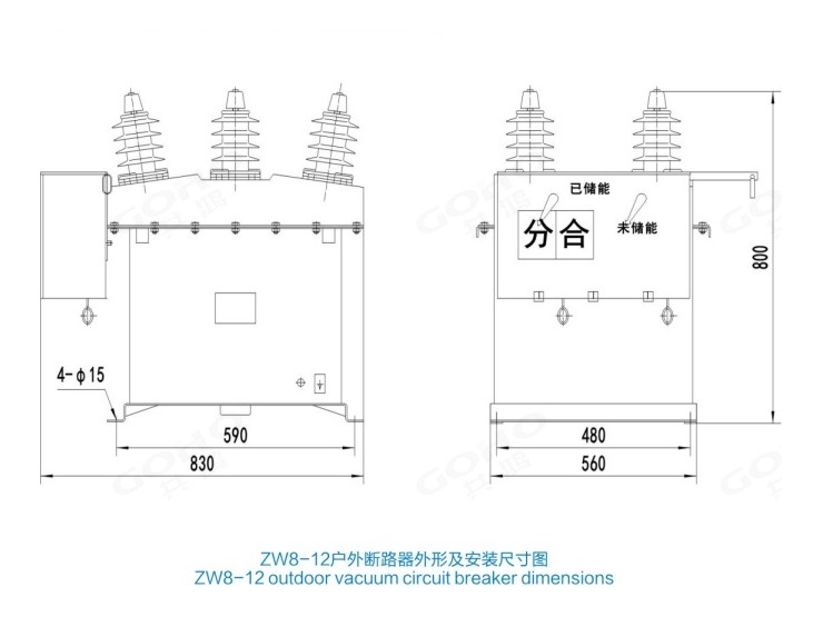
GOHO® is a registered trademark of Gonghong Electric Appliance Co., Ltd. Technical data describes the standard ZW8‑12 pole mounted outdoor vacuum circuit breaker platform and is given as typical ratings; the ratings of a specific unit follow the approved drawing and the configuration ordered. Ratings outside the table in this page, and site conditions outside the stated limits, are quoted on application. Product images are shown for illustration. Please refer to the drawing issued with your offer for dimensional and foundation data.