
VS1‑12 / ZN63A
Indoor Vacuum Circuit Breaker
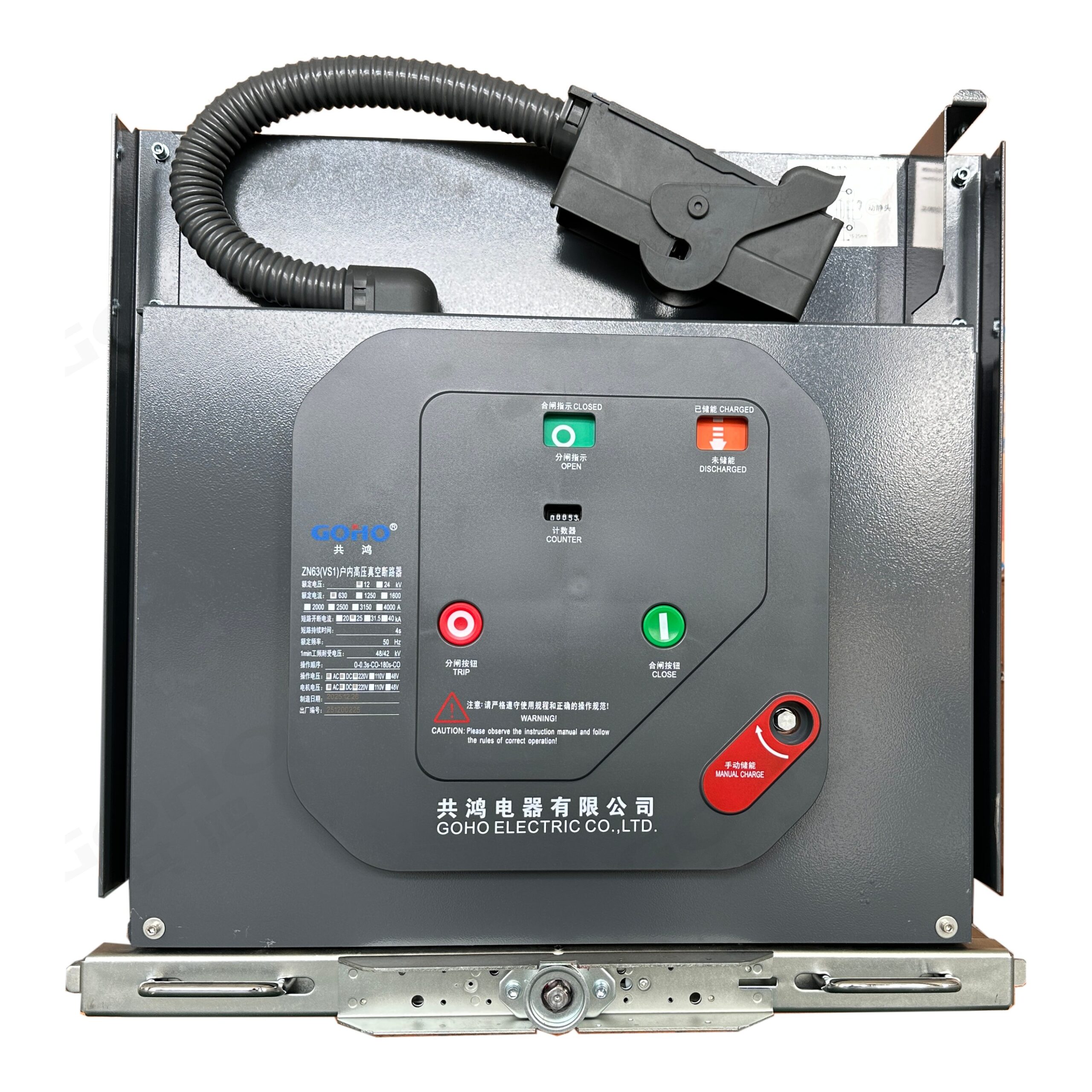
GOHO® builds the VS1‑12 (type ZN63A) three‑pole indoor vacuum circuit breaker for 12 kV distribution systems. The operating mechanism is integrated into the breaker body instead of living in a separate box, and the complete unit is mounted on a withdrawable handcart truck that runs into a KYN28A‑12 or XGN cubicle. It switches load current, overcurrent and short‑circuit current on transformer incomers, feeder circuits and motor supplies, and is used wherever a 12 kV cubicle has to be re‑energised quickly after a fault.
- Rated Voltage
- 12 kV Three-phase, 50 / 60 Hz, indoor switchgear
- Rated Normal Current
- 630 · 1250 · 1600 · 2000 · 2500 · 3150 · 4000 A One truck, seven current ratings
- Short-Circuit Breaking
- 20 · 25 · 31.5 · 40 · 50 kA Peak making 50 · 63 · 80 · 100 · 125 kA, 4 s duty
Technical Specifications
The VS1‑12 is built as a single rating family: the same interrupter pole and the same mechanism are used across the range, and the current and breaking ratings are set by the pole type, the contact assembly and the mechanism spring.
| Parameter | Value |
|---|---|
| Rated voltage Ur | 12 kV |
| Rated frequency | 50 / 60 Hz |
| Number of poles | 3 |
| Rated normal current Ir | 630 / 1250 / 1600 / 2000 / 2500 / 3150 / 4000 A |
| Rated short-circuit breaking current Isc | 20 / 25 / 31.5 / 40 / 50 kA |
| Rated short-circuit making current (peak) | 50 / 63 / 80 / 100 / 125 kA |
| Rated short-time withstand current Ik, 4 s | 20 / 25 / 31.5 / 40 / 50 kA |
| Rated peak withstand current Ip | 50 / 63 / 80 / 100 / 125 kA |
| Rated duration of short circuit | 4 s |
| Rated power-frequency withstand voltage, 1 min — phase to earth and phase to phase | 42 kV |
| Rated power-frequency withstand voltage, 1 min — across the open contacts | 48 kV |
| Rated lightning impulse withstand voltage (peak) — phase to earth and phase to phase | 75 kV |
| Rated lightning impulse withstand voltage (peak) — across the open contacts | 85 kV |
| Rated operating sequence | O – 0.3 s – CO – 180 s – CO (O – 180 s – CO – 180 s – CO at 40 kA and above) |
| Rated single capacitor bank breaking current | 630 A |
| Rated back-to-back capacitor bank breaking current | 400 A |
| Rated short-circuit breaking operations | 50 (≤ 31.5 kA) · 30 (40 kA) · 12 (50 kA) |
| Contact gap | 9 ± 1 mm |
| Contact overtravel (contact spring compression) | 3.5 ± 0.5 mm |
| Pole centre distance | 210 ± 1.5 mm (150 mm and 275 mm on request) |
| Three-phase opening / closing asynchronism | ≤ 2 ms |
| Contact bounce time on closing | ≤ 2 ms |
| Average opening speed | 1.1 ± 0.2 m/s |
| Average closing speed | 0.6 ± 0.2 m/s |
| Opening time | 20 – 50 ms |
| Closing time | 35 – 70 ms |
| Main circuit resistance per phase | ≤ 60 µΩ at 630 A, down to ≤ 25 µΩ at 2500 A and above |
| Permissible contact wear (accumulated thickness) | 3 mm |
| Rated control and auxiliary circuit voltage | DC 110 V / 220 V, AC 110 V / 220 V |
| Mechanical endurance | 20 000 operating cycles (10 000 at 40 kA and above) |
| Product standard | GB/T 1984 · GB/T 11022 · DL/T 403 · IEC 62271-100 |
Values above describe the standard VS1‑12 platform and are given as typical ratings. The rating combination of a specific breaker follows the approved drawing, the pole type and the operating mechanism ordered. A 4000 A unit is supplied for a cubicle with forced-air cooling; ratings above 4000 A and other control voltages are quoted on application.
Service Conditions
The VS1‑12 is an indoor device, so it is the switch room rather than the weather that sets the limits. Ventilation, humidity and dust in the room are part of the specification.
| Condition | Limits for standard supply |
|---|---|
| Ambient temperature | −15 °C to +40 °C |
| Average ambient temperature over 24 hours | ≤ +35 °C |
| Altitude | ≤ 1000 m (up to 3000 m on request) |
| Relative humidity, daily mean | ≤ 95 % |
| Relative humidity, monthly mean | ≤ 90 % |
| Vapour pressure, daily mean | ≤ 2.2 kPa |
| Vapour pressure, monthly mean | ≤ 1.8 kPa |
| Seismic intensity | ≤ 8 degrees |
| Electromagnetic interference, secondary system | ≤ 1.6 kV |
| Installation | Indoor, on a level foundation, in a room without fire or explosion hazard, severe pollution, chemical corrosion or violent vibration |
A switch room outside these limits — high altitude, an unheated substation, a corrosive atmosphere or a higher short-circuit level — is handled by agreement at the enquiry stage, because the pole type, the creepage distance and the mechanism heater are selected against them.
Construction & Operating Principle
Mechanism integrated into the breaker
The stored‑energy spring mechanism is built into the breaker body rather than into a separate mechanism box. That is what the VS1 designation means in practice: the spring charger, the closing and opening coils, the auxiliary switches and the tripping linkage all travel with the breaker when it is withdrawn, so a spare unit is a complete functional replacement. The mechanism is charged by a permanent‑magnet single‑phase DC motor through a reduction gear, and can also be charged by hand with the crank supplied for commissioning.
Interrupter poles
Each pole is a vacuum interrupter held in an epoxy‑resin pole, either cast around the interrupter as an embedded pole or assembled into an insulating cylinder. Embedded poles are smaller and are the usual choice where the cubicle width is tight; assembled poles can be opened for inspection. The three poles are bolted to a common frame that also carries the insulating pull rods down to the mechanism.
How it operates
On a trip command the opening spring in the mechanism drives the main shaft, and the insulating pull rods carry the movement up to the three moving contacts. The arc drawn across the separating contacts is extinguished inside the vacuum interrupter within a fraction of a cycle, and the three poles operate together inside the 2 ms asynchronism limit. Closing energises the closing coil against the closing spring; once the contacts meet, the mechanism latches and the closing spring is recharged by the motor.


Withdrawable Truck & Cubicle Compatibility
Three working positions
The truck runs between a connected position, a test position and a disconnected position. In the disconnected position the primary contacts are separated by a visible distance and the secondary plug is still engaged, so the breaker can be operated for testing without exposing the operator to the live busbar. In the test position the secondary circuits are connected and the primary circuits are not. The truck is racked between positions by the dedicated propulsion mechanism through the cubicle front, with the door closed.
Mechanical interlocks
The cubicle and the truck are interlocked so that a closed breaker cannot be racked into or out of the connected position, the breaker cannot be closed unless the truck is fully in the connected or the test position, and the earth switch cannot be closed while the truck is in the connected position. Racking with the cubicle door open is prevented. These interlocks are mechanical rather than electronic, so they hold with the control supply removed.
Cubicle compatibility
The withdrawable version is dimensioned for KYN28A‑12 (GZS1) type metal‑clad cubicles; the fixed version suits XGN fixed cubicles and GG‑1A panels. The interface dimensions and the secondary plug arrangement also let the truck replace the common 12 kV withdrawable designs, which matters when an existing switchboard is being refurbished rather than replaced.
Available Ratings & Options
The current and breaking rating are chosen independently of the cubicle, so the same switchboard can carry a light feeder and a heavy incomer without changing the panel arrangement.
The lightest ratings in the family, used on outgoing feeders and transformer incomers up to about 1.6 MVA at 12 kV. Mechanical endurance is 20 000 operating cycles at this level, which suits circuits that are switched every day.
The workhorse ratings for a 12 kV switchboard incoming breaker and for bus sectionalising. A cubicle busbar rated for 2500 A is normally ordered with the 31.5 kA pole so that the board can be extended later.

For industrial plant incomers and utility substations where the system short-circuit level is high. At 40 kA the pole uses a heavier contact assembly and the mechanism spring is uprated; the rated operating sequence changes to O – 180 s – CO – 180 s – CO.
The top of the range, supplied only with a forced-air-cooled cubicle and a confirmed busbar rating. Breaking capacity 50 kA with a peak making current of 125 kA; quoted against the system study rather than from a catalogue.
| Option | Available |
|---|---|
| Type designation | ZN63A (VS1)‑12 / T — spring operating mechanism |
| Rated normal current | 630 / 1250 / 1600 / 2000 / 2500 / 3150 / 4000 A |
| Rated short-circuit breaking current | 20 / 25 / 31.5 / 40 kA, 50 kA on application |
| Mounting | Withdrawable handcart unit or fixed unit |
| Cubicle compatibility | KYN28A‑12 (GZS1) metal-clad; XGN and GG‑1A fixed cubicles |
| Interrupter pole | Epoxy-cast embedded pole or assembled pole, to order |
| Earthing switch | Integral to the cubicle, mechanically interlocked with the truck |
| Capacitor bank switching | 630 A single bank / 400 A back-to-back, on request |
| Control and auxiliary voltage | DC 110 V / 220 V, AC 110 V / 220 V |
| Forced-air cooling | Required for the 4000 A rating |
Ratings are quoted for a specific cubicle arrangement. Send the busbar rating, the short-circuit level and the panel type with the enquiry and the truck is supplied matched to them.
Key Features
Applications
The VS1‑12 is used wherever a 12 kV indoor switchboard has to switch load, clear a fault and be restored quickly — which in practice means almost every medium voltage switch room.
- Transformer incomers in 12 kV package substations and indoor substations
- Outgoing distribution feeders in utility and industrial switchboards
- Bus sectionalising between two busbar sections of the same board
- Motor starters and motor control centre incomers, including frequent starting duty
- Capacitor bank switching where the pole is ordered for capacitor duty
- Wind and solar plant collector feeders at the MV side of the plant transformer
- Steel, cement and paper mills — heavy plant incomers on 12 kV distribution
- Mining and quarry switch rooms — feeders in dusty service conditions
- Water and pumping stations — pump feeder protection and switching
- Airports, hospitals and data centres — the MV incomer of the site substation
- Railway traction and depot substations — 12 kV feeder and sectioning breakers
- Switchboard refurbishment — replacing worn withdrawable units in existing cubicles
What We Need to Quote Your Breaker
Because the breaker is configured to the cubicle, the enquiry has to carry both the electrical duty and the panel arrangement. With the items below we can return a firm quotation and a dimensional drawing.
- System voltage, rated frequency and the earthing arrangement
- Rated normal current required at the breaker
- System short-circuit level, or the required breaking capacity
- Cubicle type and panel width — KYN28A‑12, XGN or an existing board
- Withdrawable or fixed mounting, and the required interlock scheme
- Operating mechanism and the control voltage available in the switch room
- Whether the pole is for feeder duty or capacitor bank duty
- Site conditions — altitude, ambient temperature, humidity, pollution level
Send these to gohointl@gmail.com and we will reply with a priced offer, the dimensional drawing for the cubicle interface, the secondary circuit diagram and the routine test plan.
Standards & Documentation
| Item | Reference |
|---|---|
| Product standard, China | GB/T 1984 — High-voltage alternating-current circuit-breakers |
| Common specification, China | GB/T 11022 — Common specifications for high-voltage switchgear and controlgear |
| Ordering standard, China | DL/T 403 — Ordering technical conditions for 12 kV to 40.5 kV vacuum circuit breakers |
| Product standard, international | IEC 62271-100 — High-voltage switchgear and controlgear, Part 100 |
| Routine test, main circuit | Main circuit resistance measurement and power-frequency withstand test |
| Routine test, auxiliary circuits | Wiring check and power-frequency withstand test of the control and auxiliary circuits |
| Routine test, mechanical | Contact gap and overtravel check, then a full open / close operating sequence |
| Documentation supplied | Dimensional drawing for the cubicle interface, secondary circuit diagram, routine test record and operating instructions |
Type test reports for the VS1‑12 platform and the routine test record for the individual breaker are available for project qualification on request.
Breakers are assembled in our own factory in Yueqing, Zhejiang — the same site that builds our switchgear, transformers and prefabricated substations. Pole casting or assembly, mechanism fitting, wiring and routine testing all happen in‑house, which keeps both the delivery schedule and the quality check inside our control.
GOHO® is a registered trademark of Gonghong Electric Appliance Co., Ltd. Technical data describes the standard VS1‑12 (ZN63A) indoor vacuum circuit breaker platform and is given as typical ratings; the ratings of a specific unit follow the approved drawing and the configuration ordered. Ratings outside the table in this page, and site conditions outside the stated limits, are quoted on application. Product images are shown for illustration. Please refer to the drawing issued with your offer for dimensional and foundation data.