
GHW3
Intelligent Air Circuit Breaker
GOHO® builds the GHW3 intelligent air circuit breaker as the main protective device of a low voltage switchboard. It is offered in four frame sizes from 630 A to 6300 A at 400 V and 690 V, in drawout or fixed construction, with an intelligent controller in place of the older thermal‑magnetic releases. The controller carries long‑time, short‑time, instantaneous and earth‑fault protection, and on the communication version it reports to a supervisory system over Modbus or Profibus. It is used as the incoming breaker of a main switchboard, as a generator main breaker and as a bus tie where full time grading with the downstream moulded case breakers is required.

- Rated Operational Voltage
- 400 / 690 V Three-phase, 50 / 60 Hz, utilization category B
- Rated Current
- 630 · 800 · 1000 … 6300 A Four frame sizes: 2000, 3200, 4000, 6300 A
- Breaking Capacity
- Icu 80 · 100 · 120 kA At 400 V; 50 · 65 · 85 kA at 690 V
Technical Specifications
The GHW3 is a four‑frame family. Because the frame sizes are stepped rather than continuous, the first decision in selecting one is the frame, and the current rating is then chosen inside that frame.
| Parameter | Value |
|---|---|
| Rated operational voltage Ue | AC 400 V / 690 V |
| Rated insulation voltage Ui | 800 V |
| Rated impulse withstand voltage Uimp | 8000 V |
| Rated frequency | 50 / 60 Hz |
| Number of poles | 3 / 4 |
| Frame sizes | 2000 / 3200 / 4000 / 6300 A |
| Rated current In | 630 · 800 · 1000 · 1250 · 1600 · 2000 · 2500 · 3200 · 4000 · 5000 · 6300 A |
| Utilization category | B |
| Rated ultimate short-circuit breaking capacity Icu at 400 V | 80 / 100 / 100 / 120 kA |
| Rated ultimate short-circuit breaking capacity Icu at 690 V | 50 / 65 / 65 / 85 kA |
| Rated service short-circuit breaking capacity Ics at 400 V | 65 / 80 / 80 / 100 kA |
| Rated service short-circuit breaking capacity Ics at 690 V | 50 / 50 / 65 / 75 kA |
| Rated short-time withstand current Icw, 0.4 s, at 400 V | 50 / 65 / 80 / 100 kA |
| Rated short-time withstand current Icw, 0.4 s, at 690 V | 40 / 50 / 65 / 75 kA |
| Total break time | ≤ 20 – 30 ms |
| Total closing time | ≤ 55 – 70 ms |
| Operating frequency | 20 operations per hour |
| Rated current of the neutral pole | 50 % or 100 % of In, to order |
| Mounting | Drawout type or fixed type |
| Drawout positions | Connected / test / disconnected, with mechanical safety interlocks |
| Intelligent controller | Type L (economy) / M (standard intelligent) / H (communication) |
| Protection functions | Long-time delay (overload), short-time delay, instantaneous and earth fault — four-stage LSIG |
| Metering and memory | Current and voltage display, load monitoring, thermal memory, fault recording, self-test |
| Communication | Modbus-RTU / Profibus-DP on the communication controller |
| Auxiliary equipment | Shunt release, undervoltage release (instantaneous or delayed), closing electromagnet, auxiliary contacts, mechanical interlock, key lock |
| Electrical endurance | 1000 / 500 operations depending on frame |
| Mechanical endurance | 10 000 / 5000 operating cycles depending on frame |
| Permissible ambient temperature | −5 °C to +40 °C (24 h mean ≤ +35 °C) |
| Product standard | GB/T 14048.2 · IEC 60947-1 · IEC 60947-2 |
Breaking capacities are quoted frame by frame in the table below. The values above show the range covered by the four frames; the exact Icu and Ics of the breaker offered is confirmed on the datasheet issued with the quotation, because the service breaking capacity depends on the frame, the controller fitted and the cable connection arrangement.
Frame Sizes & Breaking Capacity
The four frames are stepped so that the frame is chosen first and the current rating inside it second. A frame carries any current rating listed for it, and the breaking capacity is fixed by the frame.
| Frame | Rated current In | Icu at 400 V | Ics at 400 V | Icw, 0.4 s, at 400 V | Icu at 690 V |
|---|---|---|---|---|---|
| 2000 A | 400 – 2000 A | 80 kA | 65 kA | 50 kA | 50 kA |
| 3200 A | 2000 – 3200 A | 100 kA | 80 kA | 65 kA | 65 kA |
| 4000 A | 3200 – 4000 A | 100 kA | 80 kA | 65 – 80 kA | 65 kA |
| 6300 A | 4000 – 6300 A | 120 kA | 100 kA | 85 – 100 kA | 85 kA |
Inside each frame the current rating is set by the controller setting and the current transformers fitted, not by a different breaker. A 2000 A frame, for example, covers 400 A through 2000 A, so a switchboard can be ordered with the frame sized for the eventual load and the rating set to the present one.
Service Conditions
A low voltage air circuit breaker works inside a switchboard, so the ambient temperature inside the enclosure, the pollution degree and the prospective short-circuit current at the incoming terminals are the conditions that matter.
| Condition | Limits for standard supply |
|---|---|
| Ambient temperature | −5 °C to +40 °C |
| Average ambient temperature over 24 hours | ≤ +35 °C |
| Altitude | ≤ 2000 m |
| Relative humidity | ≤ 95 % at +25 °C, with condensation avoided by ventilation or a heater |
| Pollution degree | 3 |
| Installation category | III / IV |
| Rated impulse withstand voltage | 8000 V, referred to 2000 m altitude |
| Seismic intensity | ≤ 8 degrees |
| Installation | Indoor, inside a switchboard or an enclosure; no explosive or corrosive atmosphere, no conductive dust, no violent vibration |
Inside a closed switchboard the air temperature is typically 10 to 15 K above the room temperature. Where the calculated internal temperature exceeds +40 °C, the breaker is derated or the enclosure is ventilated — the offer states which, so that the continuous rating is not read from the wrong table.
Construction & Operating Principle
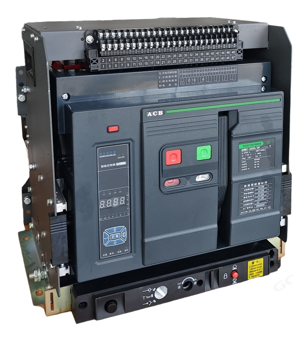
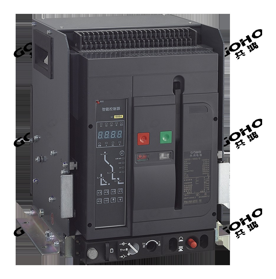
Drawout construction with three positions
The drawout version runs on rails inside the switchboard between a connected, a test and a disconnected position. The primary contacts are separated and the secondary plug is still engaged in the test position, so the breaker can be operated and its protection checked without exposing the operator to the live busbar. In the disconnected position the breaker can be lifted out and replaced from stock, which is the practical reason a main incoming breaker is usually specified as drawout: a fault in the incomer does not have to take the switchboard out of service.
Contact system and arc control
Each pole carries a main contact and an arcing contact with a splitter plate stack behind them. When the breaker opens, the arc is driven magnetically into the stack and is divided into short arcs that extinguish between the plates, and the whole process takes place inside the arc chamber. Because the arc is contained, the breaker has no external arc flash at the front of the switchboard, which is what allows the switchboard doors to be closed during operation.
Operating mechanism
The mechanism uses a closing spring charged by a motor and an opening spring. Manual charging with the handle is provided for maintenance and for use with the control supply removed. Opening is initiated by the shunt release or by the controller's trip coil; an undervoltage release is available where the breaker has to open on loss of supply as well.
Intelligent controller
The controller replaces the thermal and magnetic releases and the separate protection relay of an older design. Current transformers built into the breaker measure each phase and the neutral, and the controller evaluates them in a microprocessor against the protection settings. Because the settings are digital, the grading between the incoming breaker and the outgoing moulded case breakers can be calculated and set rather than adjusted by trial.
Intelligent Controller & Protection Functions
Three controller types
The controller is offered in three levels so that the cost matches the duty. The economy type offers the basic protection stages set by DIP switches, without a digital display. The standard intelligent type adds protection, measurement, display and alarm functions. The communication type adds the port and the protocols. Because the controller is a separate module, a standard or economy breaker can be upgraded later without replacing the breaker.
Four-stage protection
Long-time delay handles overload with a thermal memory so that a breaker that has just carried an overload trips sooner on the next one. Short-time delay provides the adjustable time grading with the downstream breakers. Instantaneous protection clears a close-up short circuit. Earth fault protection covers single-phase earth faults, with an adjustable setting and a choice of residual or source earth connection. Parameters are set by rotary dial or by keypad and are readable on the display.
Measurement and memory
The controller displays current and voltage, monitors loading, keeps a thermal image of the load, records the last fault with its values, and runs a self-test. That record is what makes a post-fault investigation possible without fitting a separate analyser: the tripping current, the phase involved and the protection stage that operated are all stored.
Selectivity and coordination
The short-time withstand current rating is what makes grading possible. A 6300 A frame holds 85 to 100 kA for 0.4 second, which is long enough for the downstream moulded case breaker to clear a fault in its own zone while the incomer waits. Without that withstand capability the incomer would have to trip instantaneously and the whole board would go dark. The same logic runs one level down between the GHM3 moulded case breakers and the DZ47 miniature breakers on the final circuits.
Accessories and interlocks
A shunt release provides remote electrical tripping, an undervoltage release opens the breaker when the supply is lost (instantaneous or delayed), a closing electromagnet works with the motor mechanism, and auxiliary contacts report the position. A mechanical interlock prevents two incoming breakers from being closed onto the same busbar at the same time, and a key lock holds the breaker open for maintenance.
Frame Sizes & Options
The frame size is set by the prospective short-circuit current at the incoming terminals and by the continuous current the board has to carry, including any planned growth.
The usual frame for a distribution board incomer and for a generator main breaker in the low hundreds of kVA. Covers a wide current range on one frame, so a board can be built for a load that is expected to grow.
For a main switchboard incomer in a large commercial building, a data centre or an industrial plant, where the transformer secondary current sits in the 2000 to 3200 A band.
Used where two transformers run in parallel on one busbar, or where a single large transformer feeds the board directly. The higher short-time withstand current is what allows full grading with the outgoing breakers.
The top frame, for a heavy industrial incomer, a large generator main breaker or a bus tie between two main boards. Supplied only against a system study because the busbar and the cable connections have to be designed for it.
| Option | Available |
|---|---|
| Poles | 3-pole or 4-pole |
| Neutral pole rating | 50 % or 100 % of In, to order |
| Mounting | Drawout type with three positions, or fixed type |
| Controller | Type L (economy) / M (standard intelligent) / H (communication) |
| Communication protocol | Modbus-RTU or Profibus-DP on the communication controller |
| Shunt release | For remote electrical tripping |
| Undervoltage release | Instantaneous or delayed action |
| Closing electromagnet | Operates with the motor-charged mechanism |
| Auxiliary and alarm contacts | For position indication and signalling |
| Mechanical interlock and key lock | For bus ties and for maintenance lockout |
A frame is quoted against the prospective short-circuit current at the incoming terminals and the busbar rating, not against the transformer rating alone. Send the system study values with the enquiry and the frame, the breaking capacity and the controller type are confirmed together.
Key Features
Applications
The GHW3 is used wherever a low voltage system needs a main protective device with a high breaking capacity and adjustable grading against the breakers downstream.
- Main switchboard incomer in industrial plants and large commercial buildings
- Transformer secondary main breaker at the LV side of a distribution substation
- Generator main breaker and generator control panel incomer
- Bus tie between two main switchboards or between two transformer secondaries
- Motor control centre incomer where several large motors start together
- Data centre and telecom room main distribution, where selectivity is essential
- Photovoltaic and wind plant LV collector incomer and inverter main breaker
- Mining, steel, cement and paper plants — heavy industrial incomers
- Marine and offshore installations, including 690 V distribution
- Hospitals, airports and rail installations, where an unnecessary trip is not acceptable
- Electric vehicle charging hubs — the incomer of a charging park
- Switchboard refurbishment — replacing an existing main breaker with the same panel opening
What We Need to Quote Your Breaker
The frame, the breaking capacity and the controller are chosen together against the system study. With the items below we can return a firm quotation and a dimension drawing for the panel opening.
- System voltage, rated frequency and the earthing arrangement
- Transformer rating and impedance, or the busbar continuous current required
- Prospective short-circuit current at the incoming terminals — this sets the frame
- Number of poles and whether the neutral has to be fully rated
- Controller type required — economy, standard intelligent or communication
- Protection settings or the grading study, if already calculated
- Mounting — drawout or fixed, and the panel opening dimensions
- Accessories — shunt release, undervoltage release, closing coil, auxiliary contacts, interlock; control voltage and quantity
Send these to gohointl@gmail.com and we will reply with a priced offer, the dimensional drawing for the panel opening, the controller setting list and the routine test plan for the breaker.
Standards & Documentation
| Item | Reference |
|---|---|
| Product standard, China | GB/T 14048.2 — Low-voltage switchgear and controlgear, circuit-breakers |
| Product standard, international | IEC 60947-2 — Low-voltage switchgear and controlgear, Part 2: Circuit-breakers |
| General rules, international | IEC 60947-1 — Low-voltage switchgear and controlgear, general rules |
| Routine test, main circuit | Main circuit resistance measurement and power-frequency withstand test |
| Routine test, auxiliary circuits | Wiring check and power-frequency withstand test of the control and auxiliary circuits |
| Routine test, protection | Controller setting and trip test at the ordered values for each protection stage |
| Routine test, mechanical | Full open / close operating sequence, drawout racking check and interlock check |
| Documentation supplied | Dimensional drawing for the panel opening, controller setting record, routine test record and operating instructions |
Type test reports for the GHW3 platform and the routine test record for the individual breaker are available for project qualification on request.

Breakers are assembled in our own factory in Yueqing, Zhejiang — the same site that builds our switchgear, transformers and prefabricated substations. Contact assembly, controller fitting and calibration, wiring and routine testing all happen in‑house, which keeps both the delivery schedule and the quality check inside our control.
GOHO® is a registered trademark of Gonghong Electric Appliance Co., Ltd. Technical data describes the standard GHW3 intelligent air circuit breaker platform and is given as typical ratings; the ratings of a specific unit follow the approved drawing and the configuration ordered. Ratings outside the table in this page, and site conditions outside the stated limits, are quoted on application. Product images are shown for illustration. Please refer to the drawing issued with your offer for dimensional and foundation data.