
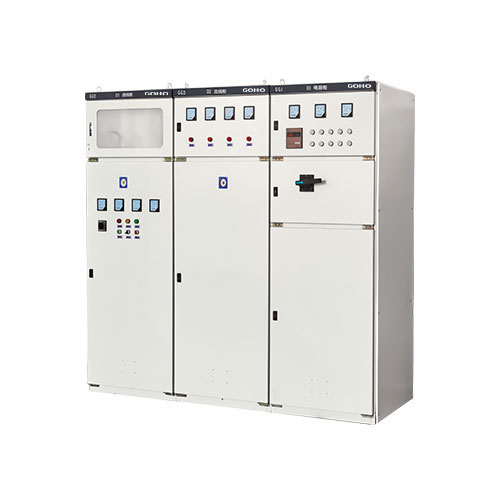
GGJ Low Voltage Reactive Power Compensation Cabinet
GGJ low voltage reactive power compensation cabinet (automatic power factor correction device) — designed to improve power factor, reduce line losses, and enhance power quality in LV distribution systems. Rated 380V/400V/415V, 30kVar–1200kVar, with intelligent microprocessor controller, self-healing MKP/MKK capacitors, and optional detuning reactors for harmonic suppression. Maintain power factor 0.92–0.99 automatically and reduce electricity costs by 5–15%.
Intelligent Automatic Power Factor Correction
Reduce electricity costs, cut line losses, and improve power quality with fully automatic capacitor compensation
The GGJ low voltage capacitor cabinet (also known as reactive power automatic compensation device) is designed to improve power factor, reduce line losses, and enhance power quality in low voltage distribution systems. Manufactured by GOHO in accordance with IEC 61439, IEC 60831, and GB/T 15576 standards, the GGJ series automatically switches capacitor banks in and out based on real-time power factor measurement, maintaining a target power factor (typically 0.92–0.99) without manual intervention.
The cabinet integrates an intelligent microprocessor-based reactive power controller, self-healing low voltage shunt capacitors (MKP/MKK metallized film type), detuning reactors (optional for harmonic suppression), and switching devices (contactor or thyristor) into a standardized metal-enclosed enclosure. The controller continuously monitors the power factor of the load side via current transformer (CT) and voltage transformer (PT) inputs and automatically switches capacitor steps to maintain the preset target power factor.
By installing GGJ capacitor cabinets, industrial and commercial users can significantly reduce electricity costs by avoiding power factor penalty charges imposed by utility companies for operation below the contractual power factor threshold (typically 0.85–0.90), while simultaneously optimizing energy consumption through reduced I²R losses in distribution cables and transformers. Typical payback periods range from 6 to 18 months depending on installed capacity and local electricity tariffs.
- 30kVar – 1200kVar capacity — modular steps from 10kVar to 100kVar each
- Automatic PF correction — maintains 0.92–0.99 without manual intervention
- Self-healing capacitors — MKP/MKK metallized film, long service life
- Optional detuning reactors — 7% or 14% for harmonic suppression
- Contactor or thyristor — cost-effective or fast TSC switching options
- 5–15% cost savings — eliminates utility PF penalty charges
Detailed Parameters
Complete technical specifications for GGJ series reactive power compensation cabinet
| Parameter | Specification |
|---|---|
| Rated Working Voltage | 380V / 400V / 415V AC |
| Rated Frequency | 50Hz / 60Hz |
| Rated Compensation Capacity | 30kVar – 1200kVar (customizable in modular steps) |
| Step Configuration | 4, 6, 8, 10, or 12 steps (automatic switching) |
| Step Capacity per Bank | 10kVar – 100kVar (configurable) |
| Target Power Factor | 0.92 – 0.99 (adjustable via controller) |
| PF Control Accuracy | ±0.01 |
| Response Time (Contactor) | ≤ 20 seconds |
| Response Time (Thyristor / TSC) | ≤ 20ms (zero-crossing switching) |
| Switching Device | AC contactor / Thyristor (TSC) |
| Controller Type | Intelligent microprocessor-based with digital display |
| Controller Inputs | CT (current) + PT (voltage) sensing |
| Controller Communication | RS485 (Modbus RTU) for remote monitoring |
| Capacitor Type | Self-healing LV shunt capacitor (MKP / MKK metallized film) |
| Capacitor Dielectric Loss | ≤ 0.2 W/kVar |
| Capacitor Overvoltage | 1.1 × Un (continuous) / 1.3 × Un (1 minute) |
| Detuning Reactor | 7% (5th/7th harmonics) or 14% (3rd harmonics) — optional |
| Harmonic Suppression | Up to 95% reduction at tuning frequency |
| Overpressure Protection | Internal disconnection device on each capacitor |
| Overvoltage Protection | Auto disconnect at ≥ 110% Un |
| Undervoltage Protection | Auto disconnect at ≤ 80% Un |
| Degree of Protection | IP30 / IP40 |
| Enclosure Material | Cold-rolled steel with epoxy powder coating |
| Cooling Method | Natural air convection (forced fan for high-capacity) |
| Ambient Temperature | -5°C to +40°C |
| Ambient Humidity | ≤ 95% (non-condensing) |
| Altitude | ≤ 2000m |
| Installation Type | Indoor, floor-standing, fixed installation |
| Standards | IEC 61439, IEC 60831, GB/T 15576 |
Why Choose GGJ Compensation Cabinet
Intelligent power factor correction that pays for itself through energy cost savings
Automatic Power Factor Correction
The intelligent microprocessor-based controller continuously monitors real-time power factor via CT and PT inputs and automatically switches capacitor banks in or out to maintain the preset target power factor (typically 0.92–0.99), eliminating the need for manual capacitor switching under varying load conditions throughout the day.
Significant Energy Cost Reduction
Power factor penalty charges for operation below the contractual threshold (typically 0.85–0.90) can increase electricity bills by 5–15% or more. The GGJ cabinet eliminates these penalties by maintaining power factor above the required threshold, with typical payback periods of 6–18 months depending on installed capacity and local tariffs.
Reduced I²R Losses
Improving power factor from 0.75 to 0.95 reduces line current by approximately 21% for the same active power delivery, correspondingly reducing I²R losses in cables, transformers, and switchgear by approximately 37% — extending equipment life, reducing cooling load, and freeing up distribution system capacity for additional loads.
Self-Healing Capacitor Technology
MKP/MKK metallized polypropylene film capacitors feature self-healing capability — in the event of a dielectric breakdown, the metallized layer around the fault point vaporizes, isolating the fault and restoring normal operation without capacitor failure, unlike conventional foil-type capacitors which would permanently short-circuit. This dramatically extends service life.
Capacitor Overpressure Disconnection
Each capacitor element is equipped with an overpressure disconnection device — in the event of end-of-life failure at maximum overpressure, the internal disconnect mechanism permanently isolates the failed element from the circuit, preventing explosive rupture or fire. This critical safety feature ensures continued safe operation even if individual capacitors reach end of life.
Optional Harmonic Protection
Integrated detuning reactors (7% or 14% tuning) prevent series and parallel resonance between the capacitor bank and system inductance, protect capacitors from harmonic overload and premature aging, and provide passive harmonic filtering. 7% tuning (189Hz) is recommended for systems with dominant 5th and 7th harmonics common with VFDs and UPS systems.
User-Friendly Digital Controller
Real-time display of power factor, voltage, current, active power, reactive power, harmonic distortion, and system status. Features password-protected parameter settings, historical data logging, and RS485 communication (Modbus RTU) for remote monitoring and SCADA/BMS integration — giving facility managers full visibility into power quality performance.
Flexible Switching Options
Standard AC contactor switching provides cost-effective operation for normal-speed applications. Optional thyristor (TSC) zero-crossing switching eliminates inrush current and transient overvoltages during capacitor switching — ideal for applications with sensitive electronic loads or frequent switching requirements where contactor arcing and wear must be minimized.
Over/Undervoltage Protection
The controller automatically disconnects capacitor banks during overvoltage conditions (≥ 110% rated voltage) and undervoltage conditions (≤ 80% rated voltage), and automatically restarts when voltage returns to the normal range — preventing capacitor damage and ensuring safe, automatic operation without manual intervention during voltage disturbances.
Where GGJ Compensation Cabinet Excels
Power factor correction and harmonic mitigation across diverse industries
Industrial Plants
Motors, welders, furnaces, compressors
Commercial Buildings
HVAC, elevators, lighting loads
Substations
Reactive compensation & voltage support
Mining
Heavy machinery PF correction
Oil & Gas
Pump stations & compressor loads
Data Centers
UPS input PF & harmonic reduction
Water Treatment
VFD pump PF correction
Infrastructure
Airports, hospitals, railways
Quality & Compliance
Certified for reliable reactive power compensation and capacitor safety
IEC 61439
LV switchgear & controlgear standard
IEC 60831
Shunt power capacitors standard
ISO 9001
Quality management system certified
GB/T 15576
Low-voltage reactive power compensation
Frequently Asked Questions
Common questions about GGJ reactive power compensation cabinets
The savings come from two sources: (1) Power factor penalty elimination — most utilities charge a penalty of 5–15% of the total electricity bill when the power factor drops below the contractual threshold (typically 0.85 or 0.90). A GGJ cabinet maintains power factor above this threshold, eliminating these penalties entirely. (2) Reduced I²R losses — improving power factor from 0.75 to 0.95 reduces line current by about 21%, cutting resistive losses in cables and transformers by approximately 37%. The combined savings typically result in a payback period of 6 to 18 months, depending on your installed capacity, current power factor, electricity tariff structure, and local penalty rates. To get an accurate estimate, provide us with your current power factor, monthly kWh consumption, and demand charge, and we'll calculate your specific savings.
Sizing a capacitor bank requires calculating the required reactive power (kVar) to raise the power factor from its current value to the target value. The formula is: Required kVar = P × (tan(φ₁) − tan(φ₂)), where P is the active power (kW), φ₁ is the current power factor angle, and φ₂ is the target power factor angle. For example, if your load is 500kW at PF 0.75 and you want to reach PF 0.95: Required kVar = 500 × (tan(acos(0.75)) − tan(acos(0.95))) = 500 × (0.882 − 0.329) = 277 kVar. A 300kVar GGJ cabinet would be suitable. Important considerations: size based on the actual load profile (not the transformer rating), account for load diversity, and avoid over-compensation which can lead to leading power factor and overvoltage. We recommend installing capacitors at approximately 70–80% of the calculated requirement to allow for load variations. Our engineers can help you size correctly based on your load data.
Detuning reactors are needed when your electrical system contains significant harmonic distortion — typically from nonlinear loads such as variable frequency drives (VFDs), UPS systems, rectifiers, welding machines, and LED lighting. Without detuning reactors, capacitors can create a parallel or series resonance with the system inductance at a harmonic frequency, causing severe harmonic amplification that can damage capacitors and other equipment. The tuning percentage determines the resonant frequency: 7% detuning means the capacitor-reactor combination resonates at 189Hz (below the 5th harmonic at 250Hz), making it effective against 5th and 7th harmonics — the most common in industrial systems with VFDs. 14% detuning resonates at 134Hz (below the 3rd harmonic at 150Hz), making it effective against 3rd harmonics common in single-phase nonlinear loads like computers and LED lighting. Choose 7% for industrial systems dominated by 5th/7th harmonics, and 14% for commercial systems with significant 3rd harmonics.
Contactor switching uses AC contactors to connect and disconnect capacitor banks. It's the standard, cost-effective solution with a response time of about 20 seconds between switching operations. Contactors produce inrush current when switching capacitors on (up to 100× rated current) and experience mechanical wear, limiting their switching frequency. Thyristor (TSC — Thyristor Switched Capacitor) switching uses solid-state thyristors to switch capacitors at the zero-crossing point of the voltage waveform. This eliminates inrush current and transient overvoltages entirely, reduces wear, and allows response times as fast as 20ms with essentially unlimited switching operations. Choose contactor switching for stable loads with infrequent switching requirements where cost is the primary concern. Choose thyristor switching for rapidly varying loads (such as cranes, elevators, or spot welders), or for installations with sensitive electronic equipment where switching transients must be avoided.
Self-healing capacitors (MKP/MKK type) use a thin metallized layer deposited on a polypropylene film dielectric. If a dielectric breakdown occurs at a weak point due to voltage stress or manufacturing defect, the high current density at the fault point causes the thin metallized layer around the fault to vaporize, effectively "healing" the capacitor by isolating the fault area. The capacitor continues to function with only a negligible loss of capacitance. This contrasts with conventional foil-type capacitors where a dielectric breakdown causes a permanent short circuit, leading to catastrophic failure, possible fire, and the need for immediate replacement. Self-healing technology dramatically extends capacitor service life (typically 100,000+ hours) and improves reliability — making it the standard for modern power factor correction applications. All GGJ cabinets use self-healing capacitors as standard.
Yes, the GGJ cabinet's intelligent controller is equipped with RS485 communication using the Modbus RTU protocol, allowing seamless integration with SCADA (Supervisory Control and Data Acquisition) systems, BMS (Building Management Systems), or industrial automation platforms. The controller can transmit real-time data including power factor, voltage, current, active power, reactive power, apparent power, harmonic distortion (THD), capacitor bank status, and alarm conditions. This enables facility managers to monitor power quality performance remotely, log historical data for energy auditing, and receive automatic alerts for abnormal conditions such as low power factor, overvoltage, or capacitor failure. For applications requiring Ethernet connectivity, we can supply controllers with Modbus TCP or Profibus options. We also offer custom integration support to ensure compatibility with your specific monitoring system.


Cut Electricity Costs with Power Factor Correction
Send us your load data — current power factor, kW demand, and harmonic profile. We'll size the right GGJ compensation solution, calculate your projected savings, and provide a factory quote with 6–18 month payback analysis.