
GHM3
Moulded Case Circuit Breaker
GOHO® builds the GHM3 moulded case circuit breaker for sub‑main and feeder protection in low voltage switchboards. Seven frame sizes cover 16 A to 1250 A at 400 V and 690 V, with breaking capacities up to 100 kA. The trip unit is thermal‑magnetic for the smaller frames and electronic for the larger ones, and the case is a sealed moulding that is not intended to be opened in service. It sits between the GHW3 air circuit breaker at the incomer and the DZ47 miniature breakers on the final circuits, and it is the device that most often decides whether a fault trips one circuit or a whole board.

- Rated Operational Voltage
- 400 / 690 V Three-phase, 50 / 60 Hz; DC 250 V on the 2-pole version
- Frame Sizes
- 63 · 125 · 250 · 400 · 630 · 800 · 1250 A Rated current 16 A to 1250 A
- Breaking Capacity
- Icu 25 – 100 kA at 400 V Three levels: L, M and H
Technical Specifications
The GHM3 is a seven‑frame family with three breaking levels in each frame. The frame sets the current range, the level sets the breaking capacity, and the trip unit type is chosen against the duty.
| Parameter | Value |
|---|---|
| Rated operational voltage Ue | AC 400 V / 415 V / 690 V (DC 250 V on the 2-pole version) |
| Rated insulation voltage Ui | 800 V |
| Rated impulse withstand voltage Uimp | 8000 V |
| Rated frequency | 50 / 60 Hz |
| Number of poles | 2 / 3 / 4 |
| Frame sizes | 63 / 125 / 250 / 400 / 630 / 800 / 1250 A |
| Rated current In | 16 · 20 · 25 · 32 · 40 · 50 · 63 · 80 · 100 · 125 · 160 · 200 · 250 · 320 · 400 · 500 · 630 · 700 · 800 · 1000 · 1250 A |
| Utilization category | A |
| Rated ultimate short-circuit breaking capacity Icu at 400 V | 25 – 100 kA, frame and level dependent |
| Rated service short-circuit breaking capacity Ics | 50 – 100 % of Icu, level dependent |
| Breaking levels | L (basic) / M (standard) / H (high) |
| Trip unit | Thermal-magnetic, fixed or adjustable; or electronic with adjustable settings |
| Electronic trip settings | Ir, Isd, Ii, tsd and Ip adjustable by rotary dial |
| Mounting | Fixed, plug-in with a base, or drawout |
| Front-face protection | IP20 |
| Flying arc distance | 0 mm on the 63 A frame; ≤ 50 mm on the 125 – 400 A frames; ≤ 100 mm on the 630 – 1250 A frames |
| Case material | Flame-retardant, impact-resistant moulding, UL94 V-0 |
| Electrical endurance | ≥ 1500 operations at rated load |
| Mechanical endurance | ≥ 8000 operating cycles |
| Permissible ambient temperature | −25 °C to +40 °C |
| Product standard | GB/T 14048.2 · IEC 60947-2 |
Breaking capacity depends on the frame, the breaking level and the trip unit, so it is quoted by frame in the table below rather than as a single figure. The exact Icu and Ics of the breaker offered is confirmed on the datasheet issued with the quotation. Ratings at 690 V are typically 60 to 75 % of the 400 V values.
Frame Sizes & Breaking Capacity
The seven frames are stepped at roughly 2:1 so that a feeder is protected by the smallest frame that covers its current, rather than by a large frame turned down. Setting a large frame to a low current wastes breaking capacity and money.
| Frame | Rated current In | Poles | Icu at 400 V | Typical Icu at 690 V |
|---|---|---|---|---|
| 63 A | 16 – 63 A | 2 / 3 / 4 | 25 – 50 kA | 20 – 35 kA |
| 125 A | 16 – 125 A | 2 / 3 / 4 | 25 – 85 kA | 20 – 50 kA |
| 250 A | 100 – 250 A | 3 / 4 | 35 – 85 kA | 25 – 50 kA |
| 400 A | 250 – 400 A | 3 / 4 | 50 – 100 kA | 35 – 65 kA |
| 630 A | 400 – 630 A | 3 / 4 | 50 – 100 kA | 35 – 65 kA |
| 800 A | 630 – 800 A | 3 / 4 | 50 – 100 kA | 35 – 65 kA |
| 1250 A | 800 – 1250 A | 3 / 4 | 50 – 85 kA | 35 – 65 kA |
The ranges above span the L, M and H breaking levels within each frame. The level is chosen against the prospective short-circuit current at the point where the breaker is installed, so the same 250 A frame can be ordered as an L for a commercial board or as an H for a point close to a large transformer.
Service Conditions
The GHM3 works inside a switchboard or a machine enclosure. The air temperature inside the enclosure and the pollution degree set the derating and the insulation requirement.
| Condition | Limits for standard supply |
|---|---|
| Ambient temperature | −25 °C to +40 °C |
| Altitude | ≤ 2000 m |
| Relative humidity | ≤ 50 % at +40 °C, higher at lower temperatures |
| Pollution degree | 3 |
| Installation category | III |
| Front-face protection | IP20 |
| Terminal capacity | To the frame: 25 mm² on the 63 A frame, up to 240 mm² or busbar connection on the 1250 A frame |
| Installation | Indoor, in a switchboard or enclosure; no explosive or corrosive atmosphere, no conductive dust |
Where the air inside the enclosure is above +40 °C, the continuous rating of the breaker is reduced. The offer states the derating for the enclosure concerned so that the frame is not selected against the wrong ambient temperature.
Construction & Operating Principle
Sealed moulded case
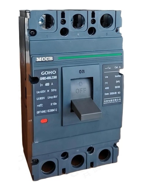
The case is a single flame‑retardant moulding that carries the current path, the mechanism and the trip unit, and it is not opened in service. The moulding insulates the live parts from the operator and from the enclosure, which is one of the reasons a moulded case breaker needs less clearance than an open air circuit breaker of the same rating. The operating handle projects through the front face and is padlockable in the open position for maintenance lockout.
Contact system and arc quenching
Each pole has a main contact that carries the current and an arcing contact that takes the arc as the contacts separate. The arc is driven magnetically into a stack of de‑ion plates and is divided into a number of short arcs that are cooled and extinguished between the plates. The current‑limiting action of the contact system shortens the let‑through energy, so a downstream breaker and cable see less thermal stress than the prospective current alone would suggest. The flying arc distance given in the table is the clearance that has to be left in front of the terminals in the enclosure.
Trip units
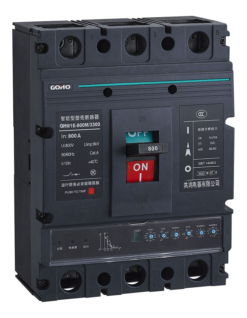
The thermal‑magnetic trip unit uses a bimetal strip for the overload range and a fixed magnetic release for short circuits; it is robust, needs no supply and is available with fixed or adjustable settings. The electronic trip unit measures the current with internal transformers and evaluates it in a microprocessor, which allows the long‑time, short‑time, instantaneous and earth‑fault settings to be dialled independently and read off the front. Electronic trip units are used on the larger frames and wherever grading with the incomer has to be calculated.
Operating mechanism
The mechanism is a toggle acting on a latch, and it is trip‑free: if the breaker trips while the handle is held in the closed position, the mechanism still releases and the contacts open. This matters where an operator is holding the handle during a fault, and it is also what makes the breaker safe to use as a local isolator with the enclosure door closed. Rotating handles, motor operators and external operating mechanisms are available where the breaker sits behind a door or a panel.
Trip Units, Accessories & Coordination
Choosing between thermal-magnetic and electronic
Thermal‑magnetic is the right default for frames up to about 250 A: it needs no auxiliary supply, it behaves predictably at high ambient temperature, and its inverse‑time curve is what makes it coordinate with the miniature breakers downstream. Electronic trip units earn their cost from about 400 A upwards, where the overload settings have to be tuned to the actual load and where the short‑time delay stage is needed to grade with the incoming air circuit breaker.
Setting the electronic trip unit
The long‑time setting Ir is set to the actual circuit current, not to the frame rating; on a 630 A frame feeding a 400 A load, Ir is set to 400 A and the frame capacity becomes headroom rather than a mis-set overload. The short‑time setting Isd and its delay tsd create the grading window with the breaker upstream. The instantaneous setting Ii is chosen above the largest downstream fault current so that the breaker does not override the protection below it.
Accessories
A shunt release trips the breaker remotely, an undervoltage release opens it when the supply is lost, a motor operator allows remote closing, and auxiliary and alarm contacts report the position and the trip. Rotary handles, extended shafts, terminal covers, phase barriers and spreaders for cable or busbar connection complete the set. Because the accessories clip onto the case, a breaker can be reconfigured at the panel works without being replaced.
Grading through the installation
The three GOHO low voltage families are designed to work as one chain. The DZ47 miniature breaker protects the final circuit, the GHM3 moulded case breaker protects the sub‑main and takes the grading decision above it, and the GHW3 air circuit breaker at the incomer holds the fault for long enough for the other two to clear their own zones. Selecting the three together, rather than purchasing them separately, is what produces a switchboard where a fault on one socket does not darken the building.
Frame Sizes & Options
The frame is chosen from the circuit current and the short-circuit level at that point, not from the rating of the switchboard as a whole. Four groups cover almost every feeder in a typical installation.
Final‑circuit and small motor protection where a miniature breaker would not have enough breaking capacity. Two-, three- and four-pole versions; the 2-pole version is also rated for 250 V DC.
The usual sub‑main frame in a commercial board or a floor distribution panel. Thermal-magnetic trip as standard, with the adjustable version where the load is not yet known.
Feeder and incomer protection in an industrial board. This is the band where the electronic trip unit starts to pay for itself, because the short-time delay stage is needed to grade with the air circuit breaker upstream.
Large feeders, generator connections and the incomer of a distribution panel that is fed from a small transformer. Supplied with an electronic trip unit and busbar or spreader terminals.
| Option | Available |
|---|---|
| Poles | 2-pole (125 A frame), 3-pole, 4-pole |
| Trip unit | Thermal-magnetic fixed or adjustable; electronic with adjustable Ir, Isd, Ii, tsd and Ip |
| Breaking level | L (basic), M (standard) or H (high), chosen per frame |
| Mounting | Fixed, plug-in with a base, or drawout |
| Connection | Cable terminals, or spreaders and busbar connection on the larger frames |
| Accessories | Shunt release, undervoltage release, motor operator, auxiliary contacts, alarm contact, rotary handle, extended shaft |
| Insulation accessories | Terminal covers, phase barriers |
| DC application | 2-pole version rated DC 250 V |
Frame, level and trip unit are quoted together against the circuit current and the prospective short-circuit current at the point of installation. Send both figures with the enquiry and the frame is confirmed rather than estimated.
Key Features
Applications
The GHM3 is used on every circuit that is larger than a final circuit and smaller than a main incomer — which in a modern installation is most of the switchboard.
- Sub-main distribution in commercial and industrial switchboards
- Feeder protection in a floor distribution panel or a rising main board
- Motor protection and motor control centre outgoing circuits
- Transformer incomer where the transformer is small enough not to need an air circuit breaker
- Generator connection and small generator main breaker
- Lighting and power distribution in a large building, per zone
- Photovoltaic and energy storage LV connections and inverter feeders
- Machine control panels and production line distribution
- Data centre and telecom room sub-distribution
- Marine, port and offshore LV distribution
- Mining, quarry and cement plant LV feeders
- Retrofit — replacing a moulded case breaker in an existing panel with the same opening
What We Need to Quote Your Breaker
The frame and the trip unit are chosen against the circuit, not against the board. With the items below we can return a firm quotation and a dimension drawing for the panel opening.
- Circuit current and the required rated current In
- Prospective short-circuit current at the point of installation — this sets the level
- System voltage, rated frequency and the number of poles required
- Whether the neutral has to be switched or fully rated
- Trip unit preference — thermal-magnetic or electronic, fixed or adjustable
- Mounting — fixed, plug-in or drawout, and the panel opening dimensions
- Accessories required — shunt release, undervoltage release, motor operator, auxiliary contacts, rotary handle
- Connection arrangement — cable or busbar; quantity and destination
Send these to gohointl@gmail.com and we will reply with a priced offer, the dimensional drawing for the panel opening, the trip setting list and the routine test plan for the breaker.
Standards & Documentation
| Item | Reference |
|---|---|
| Product standard, China | GB/T 14048.2 — Low-voltage switchgear and controlgear, circuit-breakers |
| Product standard, international | IEC 60947-2 — Low-voltage switchgear and controlgear, Part 2: Circuit-breakers |
| Case material | Flame-retardant, impact-resistant moulding to UL94 V-0 |
| Routine test, main circuit | Main circuit resistance measurement and power-frequency withstand test |
| Routine test, auxiliary circuits | Wiring check and power-frequency withstand test of the control and auxiliary circuits |
| Routine test, protection | Trip test at the ordered settings for the thermal-magnetic or electronic trip unit |
| Routine test, mechanical | Full open / close operating sequence and accessory function check |
| Documentation supplied | Dimensional drawing for the panel opening, trip setting record, routine test record and operating instructions |
Type test reports for the GHM3 platform and the routine test record for the individual breaker are available for project qualification on request.
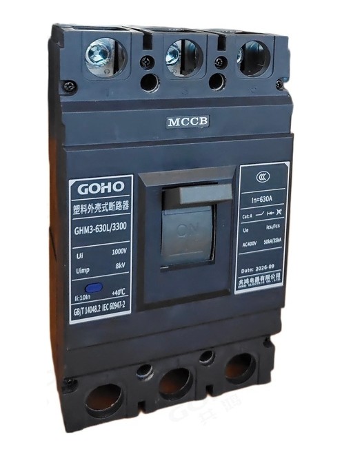
Breakers are assembled in our own factory in Yueqing, Zhejiang — the same site that builds our switchgear, transformers and prefabricated substations. Case assembly, trip unit fitting and calibration, wiring and routine testing all happen in‑house, which keeps both the delivery schedule and the quality check inside our control.
GOHO® is a registered trademark of Gonghong Electric Appliance Co., Ltd. Technical data describes the standard GHM3 moulded case circuit breaker platform and is given as typical ratings; the ratings of a specific unit follow the approved drawing and the configuration ordered. Ratings outside the table in this page, and site conditions outside the stated limits, are quoted on application. Product images are shown for illustration. Please refer to the drawing issued with your offer for dimensional and foundation data.