
ZW20‑12
Pole Mounted Sealed Tank Vacuum Circuit Breaker
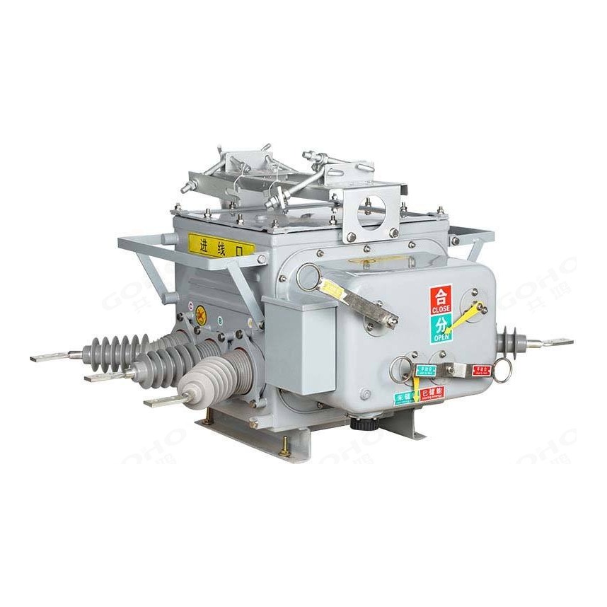
GOHO® builds the ZW20‑12 three‑pole outdoor vacuum circuit breaker around a single sealed tank. All three vacuum interrupters, the primary connections, the secondary components and the operating mechanism live inside one enclosure filled with SF6 at zero gauge pressure, and the incoming and outgoing terminals are brought out through cast silicone rubber bushings. The result is a breaker rated IP67 that needs no inspection of live parts and no topping up: it is the standard choice for a 12 kV pole‑mounted switching point, a boundary switch, or an automated sectionalising point on a city or rural network.
- Rated Voltage
- 12 kV Three-phase, 50 Hz, outdoor pole-mounted
- Rated Normal Current
- 630 · 1250 A Sealed tank design, protection IP67
- Short-Circuit Breaking
- 20 · 25 kA Peak making 50 · 63 kA, 4 s duty
Technical Specifications
Because everything primary lives inside the tank, the ZW20‑12 has fewer external parts than a column design and fewer parameters that vary between units. The table below is the standard platform.
| Parameter | Value |
|---|---|
| Rated voltage Ur | 12 kV |
| Rated frequency | 50 Hz (50 / 60 Hz on request) |
| Number of poles | 3 |
| Rated normal current Ir | 630 / 1250 A |
| Rated short-circuit breaking current Isc | 20 / 25 kA |
| Rated short-circuit making current (peak) | 50 / 63 kA |
| Rated short-time withstand current Ik, 4 s | 20 / 25 kA |
| Rated peak withstand current Ip | 50 / 63 kA |
| Rated duration of short circuit | 4 s |
| Rated power-frequency withstand voltage, 1 min (dry) — phase to earth and phase to phase | 42 kV |
| Rated power-frequency withstand voltage, 1 min (dry) — across the open contacts | 48 kV |
| Rated power-frequency withstand voltage, 1 min (wet) — phase to earth and phase to phase | 34 kV |
| Rated lightning impulse withstand voltage (peak) — phase to earth and phase to phase | 75 kV |
| Rated lightning impulse withstand voltage (peak) — across the open contacts | 85 kV |
| Power-frequency withstand voltage, secondary circuit, 1 min | 2 kV |
| Rated operating sequence | O – 0.3 s – CO – 180 s – CO |
| Rated short-circuit breaking operations | 30 |
| Contact gap | 9 ± 1 mm |
| Contact overtravel (contact spring compression) | 2.5 ± 0.5 mm |
| Three-phase opening / closing asynchronism | ≤ 2 ms |
| Average opening speed | 1.2 ± 0.2 m/s |
| Average closing speed | 0.6 ± 0.2 m/s |
| Rated control voltage | AC 220 V / DC 220 V |
| Insulating medium of the sealed tank | SF6 at zero gauge pressure, sealed for life |
| Annual leakage rate of the sealed tank | < 0.01 % |
| Enclosure protection level | IP67 |
| Weight, complete with operating mechanism | approx. 140 kg |
| Mechanical endurance | 10 000 operating cycles |
| Product standard | GB/T 1984 · GB/T 11022 · IEC 62271-100 |
Values above describe the standard ZW20‑12 platform and are given as typical ratings. The rating combination of a specific breaker follows the approved drawing, the controller fitted and the mounting arrangement ordered. Current transformer ratios inside the tank are a project item and are quoted with the offer.
Service Conditions
The sealed tank removes most of the environmental variables from the specification, but the ambient temperature range, the altitude and the pollution level still set the external insulation and the control equipment.
| Condition | Limits for standard supply |
|---|---|
| Ambient temperature | −20 °C to +50 °C |
| Maximum daily mean temperature variation | ≤ 30 K |
| Altitude | ≤ 2000 m (high-altitude version 2000 – 4000 m on request) |
| Solar radiation | ≤ 0.1 W/cm² |
| Air pollution level | Class IV |
| Ice coating thickness | ≤ 10 mm |
| Relative humidity, daily mean | ≤ 100 % |
| Relative humidity, monthly mean | ≤ 95 % |
| Seismic intensity | ≤ 8 degrees |
| Installation | Pole-mounted (suspended) or platform-mounted (fixed) on a steel frame |
The sealed construction is what makes the wide humidity range workable: because the live parts are not exposed to the outside air, high humidity and heavy pollution degrade the external bushings rather than the interrupting chamber. The bushings and the creepage distance are selected against the pollution class at the enquiry stage.
Construction & Operating Principle
One sealed tank for the whole primary circuit
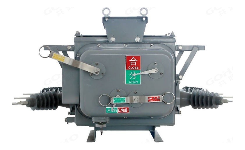
Instead of three separate columns, the ZW20‑12 encloses the three vacuum interrupters, every live part, the secondary components and the operating mechanism in a single tank. The tank is filled with SF6 at zero gauge pressure, so there is no pressure to monitor and no gas to top up over the life of the breaker, and the annual leakage rate is below 0.01 %. The internal arrangement keeps the live parts out of contact with the outside air entirely, which is what allows the enclosure to reach IP67 and what makes the breaker maintenance-free in normal service.
Silicone rubber bushings
The incoming and outgoing terminals are brought out through bushings cast as one piece in epoxy resin and silicone rubber. The cast bushing is smaller than a porcelain bushing of the same insulation level and it is hydrophobic, so water beads off the surface instead of forming a continuous conductive film. The extra insulation spacing between the terminals comes from the bushing form rather than from a longer tank, which is why the unit stays compact for a 12 kV outdoor device. The housing material is flame retardant, so a fault inside the compartment does not start a fire on the pole.
Miniaturised spring mechanism
The operating mechanism is a spring type, redesigned to fit inside the tank. It uses a direct-acting chain for the main transmission and a multi-stage tripping system, which removes the linkage that a conventional spring mechanism needs between the spring and the contact shaft. Fewer links means fewer places for wear and lost motion, and the makers' own comparison against the conventional arrangement is a several-fold improvement in repeatability. Operating power is low, so a modest control supply is enough to charge the spring.
Low-resistance main contact system
The contact between the rotating shaft and the bushing uses an inward-gripping spring contact rather than a plain wiping contact. That keeps the main circuit resistance and the temperature rise at the terminals low, which matters in a sealed enclosure where heat cannot escape as easily as from an open column design.
Automation, Mounting & Options
Pole-mounted or platform-mounted
The same breaker is installed either suspended from a pole bracket or standing on a platform frame at a small substation. Because the tank carries all the primary parts, the mounting only has to carry the weight and the short-circuit forces; there is no separate mechanism box to align with the poles during installation.
Controller and reclosing duty
With a controller fitted, the ZW20‑12 works as a recloser or as a sectionaliser. It closes back onto the line after a transient fault, counts the operations, and sections the line at the faulted span so that the healthy part of the feeder is restored before a crew arrives. Electric and manual charging, opening and closing, and local or remote control are all supported.
Primary and secondary integration
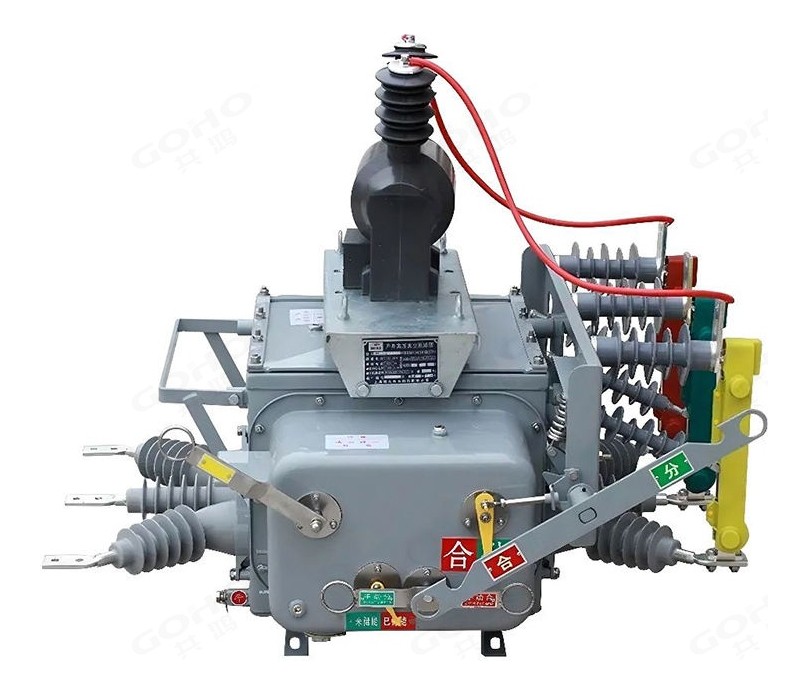
The integrated primary-and-secondary version is built for distribution automation, where the switching point has to report to the utility's system rather than simply trip. It carries protection current transformers, a zero-sequence current transformer and a zero-sequence voltage sensor, together with electronic voltage and current transducers for three-phase voltage and current measurement and two external single-phase power transformers rated 10/0.1/0.22 kV. Everything the controller needs is measured at the breaker, which removes the external instrument transformers and the wiring that would otherwise be mounted on the pole.
Explosion-proof relief
The tank carries a relief device so that if an internal fault does occur, the pressure is released away from the operating side rather than splitting the enclosure toward the line crew. It is a small part, but it is one of the reasons a sealed tank is accepted on a pole in the first place.
Available Ratings & Options
The ZW20‑12 is offered in four practical configurations. Because the tank is common to all of them, the choice is driven by the duty and by what has to be reported back to the control centre.
The usual rating for a distribution line switching or sectionalising point. Manual or motor charging, local control, and current transformers inside the tank as required by the protection scheme.
For a transformer incomer or a heavily loaded feeder where the continuous current and the system short-circuit level are both higher. Same tank, uprated interrupter and contact assembly.
An isolating switch on the same frame, mechanically interlocked with the breaker, so the line crew has a visible break. Normally specified where the unit also serves as a sectioning point.
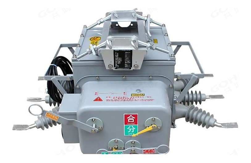
Supplied with a controller and with the protection CTs, zero-sequence CT and sensor, electronic voltage and current transducers and the external single-phase power transformers that the controller needs. Ready to connect to the utility's distribution automation system.
| Option | Available |
|---|---|
| Rated normal current | 630 A / 1250 A |
| Rated short-circuit breaking current | 20 / 25 kA |
| Current transformers | Inside the tank, ratio and accuracy class to order |
| Zero-sequence current transformer and voltage sensor | Fitted on the integrated primary-and-secondary version |
| Electronic voltage and current transducers | Three-phase voltage and current measurement on the integrated version |
| External single-phase power transformers | Two, rated 10/0.1/0.22 kV, on the integrated version |
| Controller | Reclosing and sectionalising functions; local and remote control, measurement and signalling |
| Isolating switch | Not fitted, or integral with mechanical interlock |
| Mounting | Pole-mounted (suspended) or platform-mounted (fixed) |
| Tank | Sealed, SF6 insulated, IP67 |
The current transformer ratios and the controller interface are project items. Send the protection scheme with the enquiry and the breaker is supplied with the transformer ratios and the test terminal arrangement already matched to it.
Key Features
Applications
The ZW20‑12 is used wherever a 12 kV switching point has to work outdoors with little attention — on an overhead line, at a pole substation, or at the boundary between a utility network and a customer.
- City distribution networks — switching and sectionalising on 12 kV trunk feeders
- Rural distribution networks — pole-mounted switching on long feeders
- Boundary or demarcation switches between the utility network and a customer
- Pole-mounted distribution substations — transformer incomer protection
- Line sectionalising points — isolating a faulted span
- Frequent-operation points that a plain breaker would not tolerate
- Distribution automation schemes — recloser and sectionaliser duty
- Industrial and mining sites — outdoor plant distribution feeders
- Renewable plant collector lines — switching at the plant edge
- Water supply and pumping installations — outdoor feeder switching
- Coastal, desert and heavily polluted sites — where a sealed unit is preferred
- Network upgrades — replacing oil or vacuum switches on existing poles
What We Need to Quote Your Breaker
The ZW20‑12 is configured to the line, the pole and the automation scheme. With the items below we can return a firm quotation, the outline drawing and the controller interface list.
- System voltage and rated frequency
- Rated normal current and system short-circuit level
- Whether an isolating switch or a visible break is required
- Current transformer requirement — ratio, quantity and accuracy class
- Automation requirement — plain breaker, recloser or sectionaliser
- Whether the integrated primary-and-secondary version is required
- Control supply available on the pole, or a voltage transformer to be fitted
- Mounting arrangement and site conditions — altitude, temperature, ice, pollution, wind
Send these to gohointl@gmail.com and we will reply with a priced offer, the outline drawing for the pole or platform frame, the secondary circuit diagram and the routine test plan for the breaker.
Standards & Documentation
| Item | Reference |
|---|---|
| Product standard, China | GB/T 1984 — High-voltage alternating-current circuit-breakers |
| Common specification, China | GB/T 11022 — Common specifications for high-voltage switchgear and controlgear |
| Product standard, international | IEC 62271-100 — High-voltage switchgear and controlgear, Part 100 |
| Routine test, main circuit | Main circuit resistance measurement and power-frequency withstand test |
| Routine test, auxiliary circuits | Wiring check and power-frequency withstand test of the control and auxiliary circuits |
| Routine test, sealing | Tank sealing and gas-leakage check |
| Routine test, mechanical | Contact gap and overtravel check, then a full open / close operating sequence |
| Documentation supplied | Outline drawing for the pole or platform frame, secondary circuit diagram, routine test record and operating instructions |
Type test reports for the ZW20‑12 platform and the routine test record for the individual breaker are available for project qualification on request.
Breakers are assembled in our own factory in Yueqing, Zhejiang — the same site that builds our switchgear, transformers and prefabricated substations. Tank assembly, interrupter fitting, gas filling and sealing, wiring and routine testing all happen in‑house, which keeps both the delivery schedule and the quality check inside our control.
GOHO® is a registered trademark of Gonghong Electric Appliance Co., Ltd. Technical data describes the standard ZW20‑12 pole mounted sealed tank vacuum circuit breaker platform and is given as typical ratings; the ratings of a specific unit follow the approved drawing and the configuration ordered. Ratings outside the table in this page, and site conditions outside the stated limits, are quoted on application. Product images are shown for illustration. Please refer to the drawing issued with your offer for dimensional and foundation data.