
EV Charging Station Transformers
Built for Harmonic Loads
K-factor rated distribution transformers engineered specifically for DC fast charging infrastructure. Oil-immersed and dry-type options from 30 to 2500 kVA — deployed in 30+ countries with a 2-year warranty.
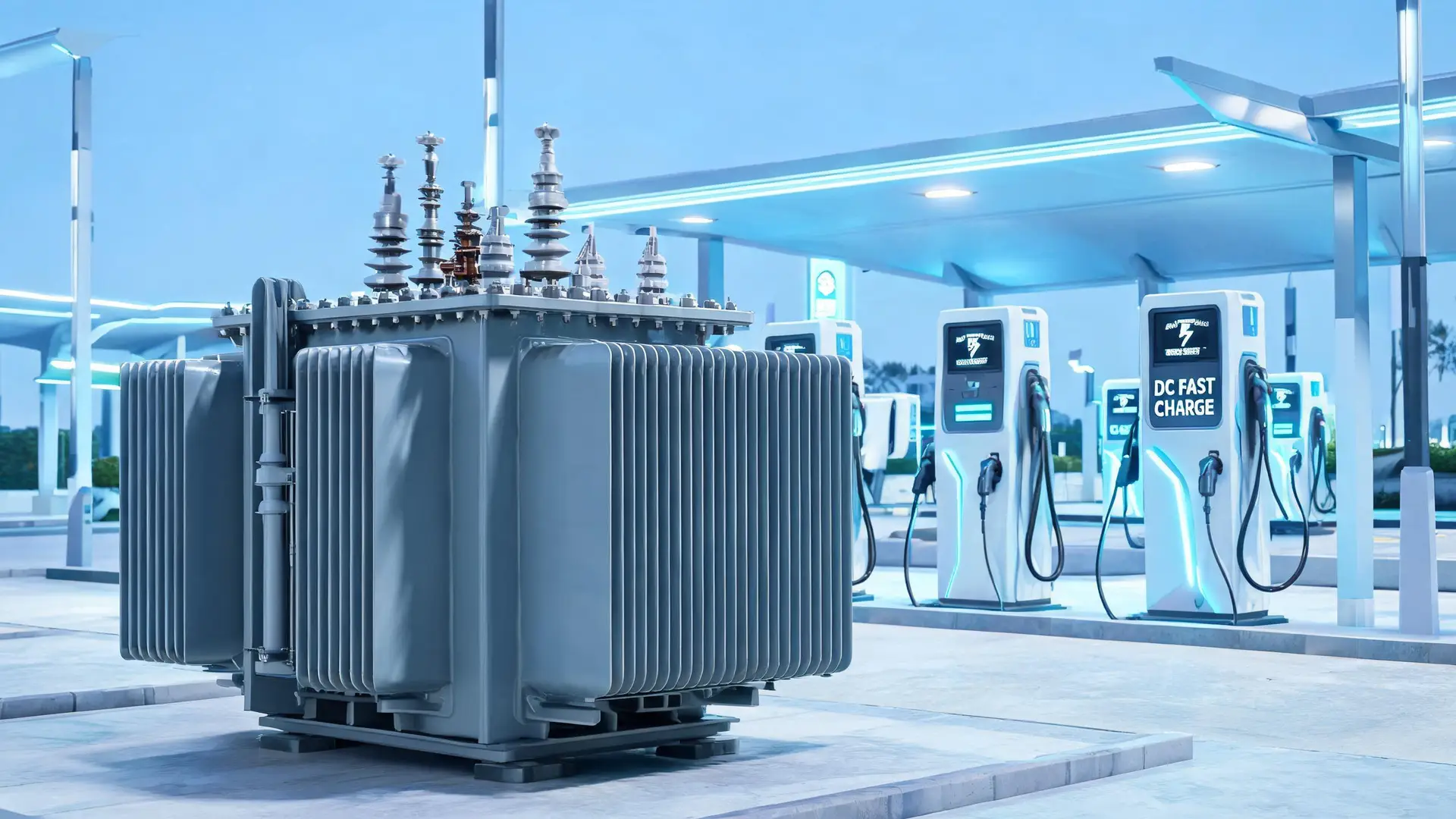
Global EV Charging Infrastructure Is Booming
The electric vehicle charging market is expanding at unprecedented speed. Here is what you need to know about the global landscape — and why transformer selection matters more than ever.
(End of 2025)
Record Growth Year
YoY Expansion
Premium Segment Rising
Transformers Engineered for EV Charging Demands
EV chargers generate significant harmonic distortion that standard transformers cannot handle. GOHO K-factor rated transformers are purpose-built for the nonlinear loads of DC fast charging stations.
K-Factor Rated
K-13 rated winding design handles harmonic loads from EV chargers without excessive overheating or premature insulation failure.
IEC 60076 Certified
Fully compliant with IEC 60076 power transformer standards, including temperature rise, dielectric, and short-circuit withstand tests.
30+ Countries Deployed
Trusted by charging operators and EPCs across Europe, Southeast Asia, the Middle East, Africa, and the Americas.
2-Year Warranty
Standard 2-year product warranty with optional 5-year extended coverage, backed by factory engineering support.
Key Performance Indicators
GOHO EV charging transformers deliver industry-leading efficiency, capacity range, and global reliability.
Why EV Charging Transformers Are Different From Standard Units
DC fast chargers impose unique stresses on distribution transformers. Understanding these differences is critical for reliable, long-lasting charging infrastructure.
Non-Linear Loads & Harmonic Distortion
DC fast chargers use rectifier circuits that draw non-sinusoidal current from the grid. Unlike linear loads (lighting, motors) that draw smooth sine-wave current, EV chargers create harmonic distortion — typically 25–35% Total Harmonic Distortion (THDi) for 6-pulse rectifiers. These harmonic currents cause additional heating in transformer windings, core, and structural components that standard transformers are not designed to handle.
Excessive Heating & Insulation Degradation
Harmonic currents generate extra I²R losses in transformer windings. The skin effect further amplifies losses at higher harmonic frequencies. Every 10°C increase in winding temperature roughly halves the insulation life. A standard transformer under EV charging loads can see its service life reduced by 30–50% due to chronic overheating from harmonic content.
K-Factor Rating Explained
K-factor is a measure of a transformer’s ability to handle harmonic heating. A K-13 rated transformer can withstand 13 times the harmonic heating of a standard (K-1) transformer. This is achieved through oversized neutral conductors (200% rating), specially transposed winding geometry, increased thermal capacity, and optimized cooling systems. For most EV charging stations with 6-pulse rectifiers, K-13 is the industry standard specification.
Rapid Load Cycling & Inrush Currents
EV charging stations experience highly variable load patterns — from near-zero during off-peak hours to full capacity during peak times. This rapid cycling creates thermal stress on windings and insulation. Additionally, multiple chargers starting simultaneously can create significant inrush currents. K-factor rated transformers with reinforced winding structures handle these dynamic conditions far better than standard distribution transformers.
| Parameter | Limit | Standard |
|---|---|---|
| Voltage THD | < 5% | IEEE 519 |
| Current TDD (I_L / I_Lmax) | 8–15% | Depends on I_sc / I_L |
| Individual Odd Harmonics | 4–7% | 3rd to 11th order |
| Neutral Current (3-phase) | Up to 173% | With 3rd harmonic |
K-Factor Rating Selection Guide
Choose the right K-factor rating based on your charger type and harmonic profile. Higher K-factor ratings provide greater protection against harmonic heating but come at a higher cost.
K-Factor Ratings & Typical EV Charging Applications
Compare K-factor levels and select the right transformer for your charging infrastructure
| K-Factor Rating | Harmonic Heating Capacity | Typical Applications | EV Charger Type | Recommendation |
|---|---|---|---|---|
| K-1 | Standard (1×) | Linear loads: lighting, resistive heating, standard motors | Level 1 / Level 2 AC chargers only | Not recommended for DCFC |
| K-4 | 4× harmonic heating | Office buildings, data centers, moderate VFD loads | Mixed AC + small DCFC (≤50 kW) | Marginal for DC fast charging |
| K-7 | 7× harmonic heating | Industrial plants with VFDs, UPS systems, hospital equipment | Medium-power DCFC (50–100 kW) | Suitable for low-power DCFC |
| K-13 | 13× harmonic heating | Heavy industrial, welding equipment, 6-pulse rectifiers | Standard DCFC (100–250 kW) | RECOMMENDED — Industry Standard |
| K-20 | 20× harmonic heating | Very high harmonic environments, 12-pulse rectifiers, heavy industrial | Ultra-fast chargers (350kW+), 12-pulse rectifier systems | For high-power ultra-fast charging |
Two Transformer Technologies, One Goal: Reliable EV Charging
Choose between oil-immersed transformers for outdoor substations and dry-type transformers for indoor or fire-sensitive installations.
Oil-Immersed Transformers
S11 / S13 / S20 / S22 Series · 30–2500 kVA
| Parameter | Specification |
|---|---|
| Models | S11, S13, S20, S22 |
| Capacity Range | 30 – 2500 kVA |
| Primary Voltage | 10 kV / 20 kV |
| Secondary Voltage | 0.4 kV (400V) |
| Vector Group | Dyn11 |
| Cooling | ONAN / ONAF |
| Efficiency Class | Up to S22 (top tier) |
| Installation | Outdoor / Pad-mounted |
Dry-Type Transformers
SCB10 / SCB11 / SCB12 / SCB13 Series · 30–2500 kVA
| Parameter | Specification |
|---|---|
| Models | SCB10, SCB11, SCB12, SCB13 |
| Capacity Range | 30 – 2500 kVA |
| Primary Voltage | 10 kV / 20 kV |
| Secondary Voltage | 0.4 kV (400V) |
| Vector Group | Dyn11 |
| Cooling | AN / AF (air natural / forced) |
| Insulation Class | F / H |
| Installation | Indoor / Enclosed areas |
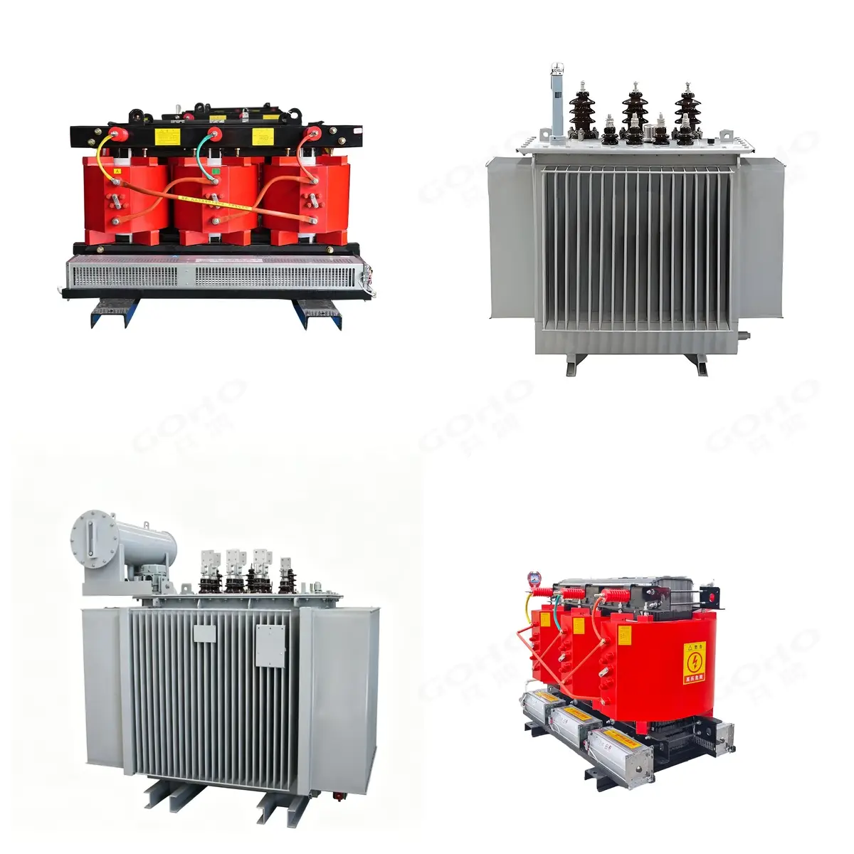
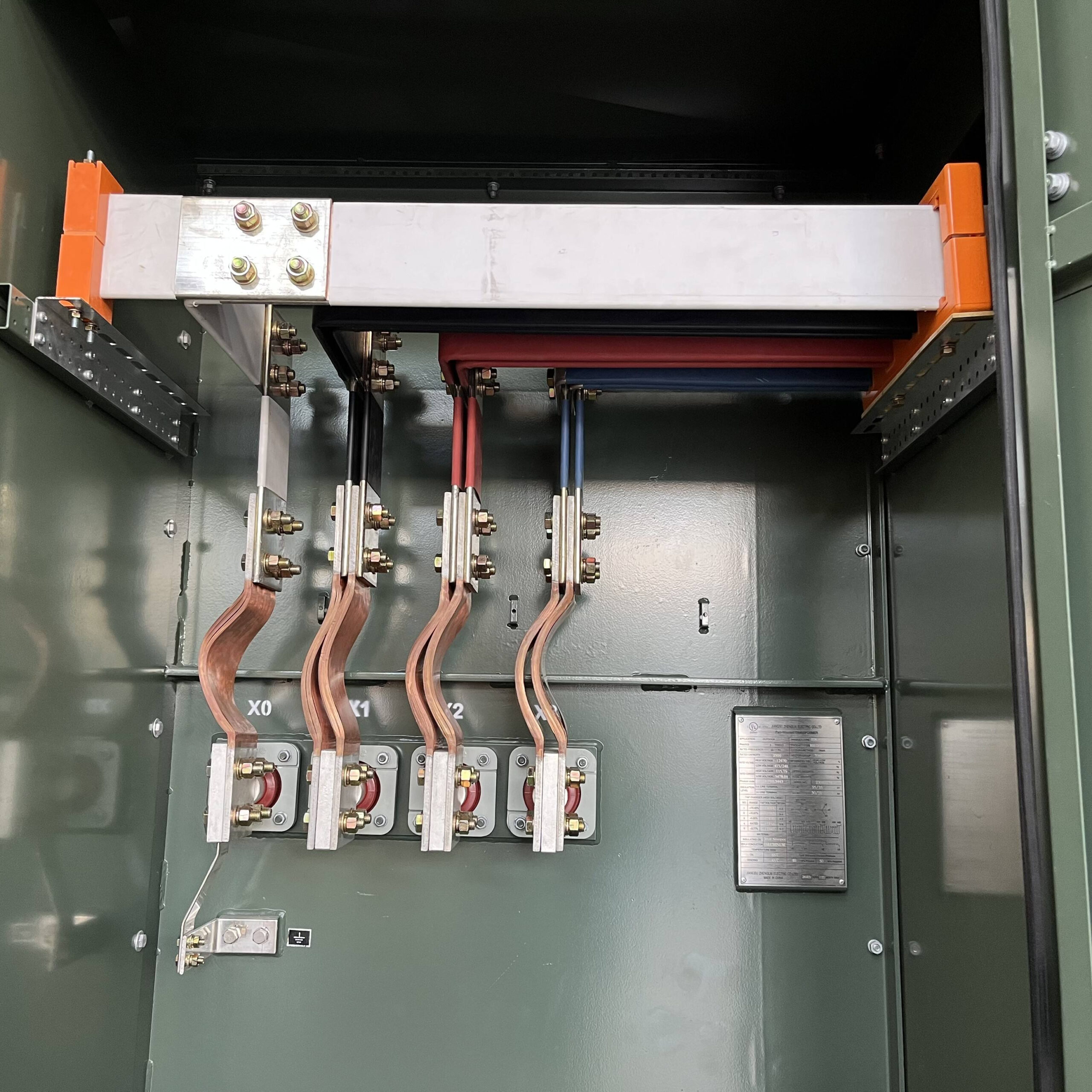
EV Charging Transformer Product Range
From compact dry-type units to heavy-duty pad-mounted substations — explore our complete range of EV charging transformers and integrated solutions.
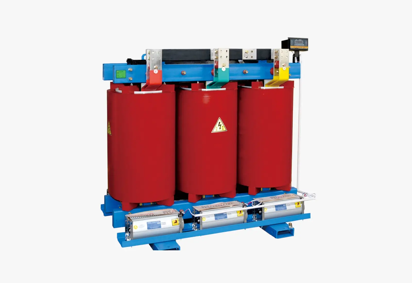
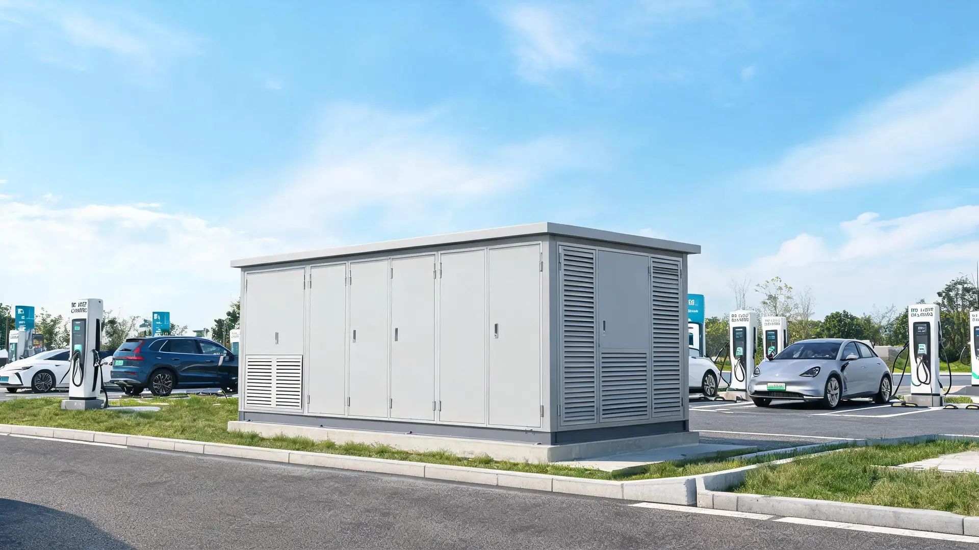
SCB Series Dry-Type Transformer Specifications
Cast resin dry-type transformers engineered for EV charging applications. K-13 rated, F/H insulation class, and IEC 60076-11 certified.
SCB Series Technical Parameters (EV Charging Configuration)
Standard models from 500 to 2500 kVA — custom capacities available on request
| Parameter | 500 kVA | 800 kVA | 1000 kVA | 1250 kVA | 1600 kVA | 2000 kVA | 2500 kVA |
|---|---|---|---|---|---|---|---|
| Rated Capacity | 500 kVA | 800 kVA | 1000 kVA | 1250 kVA | 1600 kVA | 2000 kVA | 2500 kVA |
| Voltage Ratio | 10 / 0.4 kV (10.5 / 0.4 kV, 11 / 0.4 kV, 20 / 0.4 kV available) | ||||||
| Vector Group | Dyn11 (Yyn0, Yd11 available) | ||||||
| Insulation Class | F Class (155°C) / H Class (180°C) optional | ||||||
| Impedance Voltage | 4.0% | 4.5% | 4.5% | 5.0% | 5.5% | 6.0% | 6.0% |
| Temperature Rise (Winding) | ≤ 100 K (F class) | ≤ 125 K (H class) | |||||
| No-Load Loss (SCB13) | 920 W | 1,300 W | 1,550 W | 1,800 W | 2,200 W | 2,600 W | 3,100 W |
| Load Loss (SCB13, 75°C) | 4,800 W | 6,900 W | 8,200 W | 9,800 W | 12,000 W | 14,500 W | 17,500 W |
| K-Factor Rating | K-13 (standard for EV model) / K-20 (optional) | ||||||
| Cooling Method | AN (Air Natural) / AF (Air Forced with fans) | ||||||
| Noise Level (AN mode) | ≤ 62 dB (F class) / ≤ 65 dB (H class) | ||||||
| Neutral Conductor | 200% rated (for K-13 harmonic loads) | ||||||
| Tap Changer | Off-circuit ±2×2.5% (5 positions) | ||||||
| Temperature Monitoring | PT100 sensors with 4-20mA output, alarm & trip contacts | ||||||
| Fire Safety Rating | F1 (self-extinguishing), no toxic gases | ||||||
| Standard Compliance | IEC 60076-11, GB 1094, CQC Certified | ||||||

Efficiency Class Comparison: S11 vs S13 vs S20 vs S22
Higher efficiency classes dramatically reduce no-load losses, cutting 24/7 idle energy costs for always-on EV charging stations.
| Capacity (kVA) | S11 No-Load Loss | S13 No-Load Loss | S20 No-Load Loss | S22 No-Load Loss | S22 vs S11 Savings |
|---|---|---|---|---|---|
| 100 kVA | 320 W | 230 W | 150 W | 105 W | −67% |
| 315 kVA | 670 W | 480 W | 320 W | 230 W | −66% |
| 630 kVA | 1,150 W | 810 W | 540 W | 390 W | −66% |
| 1000 kVA | 1,700 W | 1,200 W | 810 W | 580 W | −66% |
| 1600 kVA | 2,400 W | 1,700 W | 1,150 W | 830 W | −65% |
| 2500 kVA | 3,400 W | 2,400 W | 1,650 W | 1,190 W | −65% |
Transformer Sizing Quick Reference & Diversity Factors
Accurate transformer sizing requires understanding both the charger power rating and the diversity factor — how many chargers are likely to operate simultaneously at full power.
Transformer Sizing by Charger Count
Quick lookup: number of chargers to recommended kVA (120-250kW DCFC)
| Chargers (120–250 kW) | Total Power | Recommended Transformer | Station Type |
|---|---|---|---|
| 4 Chargers | ~480–1000 kW | 500 kVA | Small urban hub |
| 8 Chargers | ~960–2000 kW | 1000 kVA | Medium charging hub |
| 12 Chargers | ~1.4–3.0 MW | 1250 kVA | Highway rest stop |
| 20 Chargers | ~2.4–5.0 MW | 2000 kVA | Regional super hub |
| 30 Chargers | ~3.6–7.5 MW | 2500 kVA | Flagship charging hub |
Diversity Factor by Application Type
Simultaneity factor — percentage of chargers operating at full power simultaneously
| Application Type | Diversity Factor | Explanation |
|---|---|---|
| Public Fast Charging Station | 0.8 – 1.0 | High utilization during peak hours, all chargers likely active simultaneously |
| Fleet Depot / Logistics | 0.7 – 0.8 | Scheduled charging, staggered start times reduce peak demand |
| Commercial Parking / Mall | 0.6 – 0.7 | Mixed usage patterns, lower probability of all chargers at full power |
| Residential / Apartment | 0.4 – 0.6 | Mostly overnight charging with diverse start times and power levels |
Transformer Sizing Calculator: Step-by-Step Method
Follow this engineering methodology to properly size a transformer for your EV charging station. Correct sizing ensures reliability, efficiency, and compliance with utility requirements.
Total Charger Power
Sum the nameplate power of all chargers: P_total = N × P_charger
Apply Diversity Factor
Multiply by simultaneity factor: P_diversity = P_total × DF
Power Factor Adjustment
Divide by power factor: S_apparent = P_diversity / PF
Harmonic Derating
Apply K-factor derating or use K-rated transformer
Future Expansion Margin
Add 20–30% capacity buffer for future charger additions
Worked Example: 8 × 150 kW DC Fast Chargers at Public Station
Step-by-step calculation for a typical highway charging hub
| Step | Calculation | Value Used | Result |
|---|---|---|---|
| 1 | Total charger power: N × P_charger | 8 × 150 kW | 1,200 kW |
| 2 | Diversity factor applied (public station) | DF = 0.85 | 1,200 × 0.85 = 1,020 kW |
| 3 | Power factor correction | PF = 0.96 | 1,020 / 0.96 = 1,062.5 kVA |
| 4 | K-13 derating factor | K_derate = 0.9 | 1,062.5 / 0.9 = 1,180.6 kVA |
| 5 | Future expansion margin (25%) | M = 0.25 | 1,180.6 × 1.25 = 1,475.7 kVA |
| — | Round up to standard size | Next standard kVA | 1,600 kVA (or 2 × 800 kVA) |
Transformer Sizing by Station Capacity
Use this quick reference to estimate transformer kVA for common EV charging station sizes. For a precise calculation, our engineers consider simultaneity factors, harmonic loading, and future expansion.
| Station Size | Charger Configuration | Recommended Transformer | Model | Use Case |
|---|---|---|---|---|
| 500 kW | 4 × 120 kW DCFC | 630 kVA | S13-630/10 | Small urban charging hub |
| 1 MW | 8 × 120 kW or 4 × 240 kW | 1250 kVA | S13-1250/10 | Highway rest stop |
| 2 MW | 10 × 200 kW or 6 × 350 kW | 2000 kVA | S22-2000/10 | Regional charging hub |
| 4 MW | 20 × 200 kW or 12 × 350 kW | 2 × 2000 kVA | S22-2000/10 (dual) | Fleet depot / superhub |
5 Common Transformer Sizing Mistakes & Their Consequences
Many EV charging projects suffer from preventable transformer sizing errors. Here are the most common mistakes and why they cost you money in the long run.
1. Sizing by Nameplate Power Only
Simply adding up charger nameplate power ratings without considering diversity factor, power factor, or harmonic derating leads to oversized transformers with higher capital costs and under-loaded operation (reducing efficiency).
2. Ignoring Harmonic Loading (No K-Factor)
Using a standard K-1 distribution transformer for DC fast charging applications. This is the single most common and most dangerous mistake in EV charging transformer specification.
3. Forgetting Future Expansion
Sizing the transformer for exactly the current number of chargers without planning for future expansion. EV charging demand grows faster than most operators anticipate.
4. Underestimating Diversity at Public Stations
Applying residential or commercial diversity factors (0.4–0.6) to public fast charging stations. Public DCFC stations have much higher simultaneous usage, especially during peak travel times.
5. Neglecting Ambient Temperature & Altitude
Using standard temperature rise ratings without considering the installation environment. High ambient temperatures or high altitude installations reduce a transformer’s effective capacity.
6. Not Coordinating with Utility Grid Requirements
Sizing the transformer without consulting the local utility about grid connection capacity, fault current limits, and power quality requirements (including IEEE 519 harmonic limits).
Why K-Factor Rating Matters for EV Charging
DC fast chargers create harmonic distortion that damages standard transformers. K-factor rated transformers are built to handle these nonlinear loads.
Standard Transformers Fail Under Harmonic Loads
DC fast chargers draw non-sinusoidal current, creating harmonic distortion that adds extra heat in transformer windings. Without K-factor rating, a standard transformer will overheat, accelerating insulation aging and shortening service life by 30–50%.
Extra Heat from Harmonics
Harmonic currents generate additional I²R losses in windings, core, and structural parts — increasing temperature rise beyond design limits.
Reduced Service Life
Every 10°C above rated temperature halves the insulation life. K-13 rated windings maintain safe temperatures even with 28% THDi.
How K-Factor Works
Oversized neutral conductor (200%), specially transposed windings, and increased thermal capacity handle up to 13× the harmonic heating effect.
K-13 Is the Sweet Spot
For most EV charging stations with 6-pulse rectifiers (THDi ~25–30%), K-13 rating provides optimal protection without over-engineering.
Built Specifically for EV Charging Loads
Every GOHO EV charging transformer comes with features that directly address the unique challenges of DC fast charging infrastructure.
- ✓
K-13 Rated Winding for Harmonic Loads
Oversized neutral conductor and specially designed winding geometry handle up to 13× the rated harmonic heating effect — essential for the 6-pulse and 12-pulse rectifiers in DC fast chargers.
- ✓
Low No-Load Loss (S22 Efficiency Class)
S22 class amorphous or high-permeability silicon steel cores reduce no-load losses by up to 40% compared to standard S11 units, lowering your 24/7 idle energy cost significantly.
- ✓
High Short-Circuit Strength
Reinforced winding structure with bracing and clamping withstands the high inrush currents and fault conditions common in charging stations with multiple high-power rectifiers.
- ✓
Temperature Monitoring with Alarm/Trip
PT100 sensors (oil-immersed) or Pt100 windings (dry-type) with multi-stage alarm and trip outputs integrate directly with your SCADA or BMS system for remote monitoring.
- ✓
Off-Circuit Tap Changer (±2×2.5%)
Five-position off-circuit tap changer (±2×2.5%) compensates for grid voltage variations, ensuring optimal output voltage even in weak grid conditions common at rural highway sites.
Need a Complete Charging Station Solution?
Pair our transformers with GOHO prefabricated substations for a turnkey medium-voltage to low-voltage solution — fully assembled and tested at the factory.
- Integrated RMU, transformer & LV switchgear
- Plug-and-play commissioning
- Customized for your charger layout
- IEC 62271 & IEC 60076 compliant
Where GOHO EV Transformers Are Deployed
From remote highway rest stops to dense urban charging hubs, GOHO transformers deliver reliable power for every EV charging application.
Highway Rest Stops
Outdoor pad-mounted oil-immersed transformers for corridor fast charging
Urban Charging Hubs
Dry-type transformers for indoor and underground parking installations
Fleet Depots
Heavy-duty transformers for delivery van, bus, and truck depots
Solar + Storage + Charging
Bi-directional compatible transformers for integrated energy systems
Residential Communities
Low-noise transformers for apartment and condominium charging
Oil-Immersed vs Dry-Type: At a Glance
Two proven technologies — each optimized for different EV charging environments.
Oil-Immersed
S11 / S13 / S20 / S22 Series
- Higher efficiency (up to 99.5% at S22 class)
- Lower capital cost (10–25% less than dry-type)
- Better overload capability with oil cooling
- Longer service life (25–30 years typical)
- Lower noise levels (50–58 dB)
- Proven reliability in outdoor environments
- ONAN/ONAF cooling for heavy-duty cycling
Dry-Type
SCB10 / SCB11 / SCB12 / SCB13 Series
- No flammable oil — F1 fire safety rating
- Safe for indoor and underground installation
- Minimal maintenance (no oil testing)
- F/H insulation class for high temps
- Fast installation in existing buildings
- Environmentally friendly (no oil disposal)
- K-13 rating standard on EV models
| Feature | Oil-Immersed (S11/S13/S20/S22) | Dry-Type (SCB10/SCB11/SCB12/SCB13) |
|---|---|---|
| Capacity Range | 30 – 2500 kVA | 30 – 2500 kVA |
| Voltage Rating | 10 kV / 20 kV → 0.4 kV | 10 kV / 20 kV → 0.4 kV |
| Cooling Method | Mineral oil, ONAN / ONAF | Air, AN / AF |
| Fire Risk | Higher (flammable oil) | Low (self-extinguishing) |
| Installation Location | Outdoor / substations | Indoor / buildings / basements |
| Efficiency (at 50% load) | 98.5 – 99.0% (S22) | 97.8 – 98.5% (SCB13) |
| Noise Level | ~50 – 58 dB | ~55 – 65 dB |
| Maintenance | Oil testing every 2–3 years | Periodic cleaning only |
| Capital Cost | Lower (10–25% less) | Higher |
| K-Factor Rating | K-13 (optional) | K-13 (standard for EV model) |
| IEC Standard | IEC 60076 | IEC 60076-11 |
| Typical EV Application | Highway rest stops, fleet depots | Urban hubs, shopping malls, parking garages |
Installation & Maintenance Best Practices
Proper installation and regular maintenance ensure your EV charging transformer delivers reliable service for 25+ years. Follow these guidelines to maximize performance and lifespan.
Installation Best Practices
- Ensure proper foundation with load-bearing capacity
- Maintain minimum clearance per IEC 60076
- Install on level, vibration-free surface
- Provide adequate ventilation (especially dry-type)
- Verify grounding resistance ≤ 4Ω
- Follow phasing and rotation verification
- Perform insulation resistance test before energization
Regular Inspection Schedule
- Monthly: Visual inspection, temperature check
- Quarterly: Terminal tightness, fan operation (dry-type)
- Semi-annually: Oil sample test (oil-immersed only)
- Annually: Insulation resistance, ratio test
- Every 2–3 years: Full dielectric test
- Every 5 years: Internal inspection (if accessible)
- Monitor load profile and harmonic content yearly
EV Charging-Specific Tips
- Monitor winding temperatures during peak charging hours
- Check for unusual noise or vibration from harmonic loads
- Verify neutral current doesn’t exceed 200% rating
- Inspect cable connections for overheating signs
- Keep ventilation paths clear of dust and debris
- Log THD measurements to track harmonic trends
- Plan load growth — upgrade before reaching 90% capacity
600 kW Charging Hub — East China
See how GOHO transformers perform under real-world EV charging conditions.
600 kW Urban Charging Hub with GOHO S13-800/10 Transformer
6 × 100 kW DC fast chargers at a commercial complex in Hangzhou, China — 12 months of operational data analyzed
Station Capacity
600 kW
Transformer Model
S13-800/10
Chargers
6 × 100 kW DCFC
Commissioned
March 2025
Performance Results (12-Month Average)
| Metric | Measured Value | Design Limit | Assessment |
|---|---|---|---|
| Peak Load Factor | 78% | 100% | Well within rating — 22% headroom for expansion |
| Top Oil Temperature Rise | 52 K | 60 K (IEC limit) | 13% below IEC 60076 limit |
| Transformer Efficiency | 98.6% | ≥ 98.0% (S13 class) | Exceeds S13 efficiency guarantee |
| Current THDi (LV side) | 28.4% | — | K-13 winding handles harmonics without overheating |
| Average Daily Energy Loss | 24.8 kWh | — | Low no-load loss reduces idle cost |
Key Takeaway: The K-13 rated winding maintained stable winding temperatures despite 28% THDi from the DC charger rectifiers, confirming that standard transformers would have experienced accelerated aging at this site.
From Quote to Commissioning: Typical Project Timeline
GOHO delivers fast turnaround for EV charging projects. Here’s what to expect from order to energization.
| Phase | Duration | What’s Included |
|---|---|---|
| 1. Quote & Engineering | 2 – 5 days | Free sizing calculation, technical proposal, and competitive quote. Custom drawing review and approval if needed. |
| 2. Manufacturing | 15 – 30 days | Standard models ship in 15–20 days. Custom configurations (special voltages, K-factor, accessories) take 25–30 days. Full type tests available. |
| 3. Shipping & Delivery | 15 – 45 days | Sea freight to major ports (25–45 days). Air freight available for urgent orders (3–7 days). EXW, FOB, CIF, and DDP terms available. |
| 4. Installation | 1 – 3 days | Pad-mounted transformer installation, grounding, and LV/HV cable connections. Prefabricated substations install in 1 day with plug-and-play design. |
| 5. Commissioning | 1 day | Energization, ratio test, insulation resistance check, and temperature verification. Remote commissioning support available via video call. |
Certified Quality, Factory-Direct Reliability
Every GOHO transformer undergoes rigorous testing and holds international certifications, ensuring the highest quality standards for your EV charging infrastructure.
Certifications & Test Reports
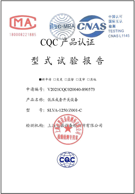
CQC Type Test Report
China Quality Certification Centre — verified performance and safety testing
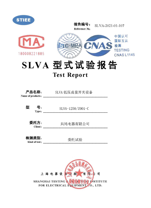
Full Type Test Report
Complete dielectric, temperature rise, and short-circuit withstand testing

IEC 60076 Certified Production
ISO 9001:2015 quality management system certified manufacturing facility
Manufacturing Capability
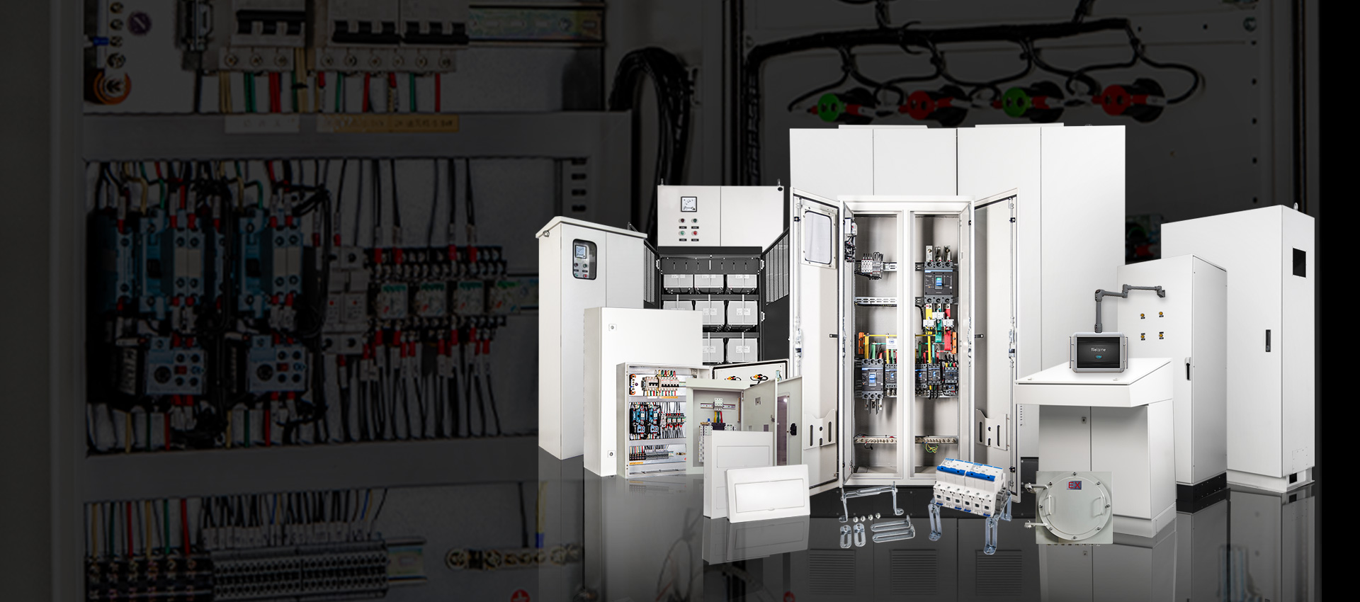
Modern Assembly Workshop
Precision winding and assembly with automated production lines
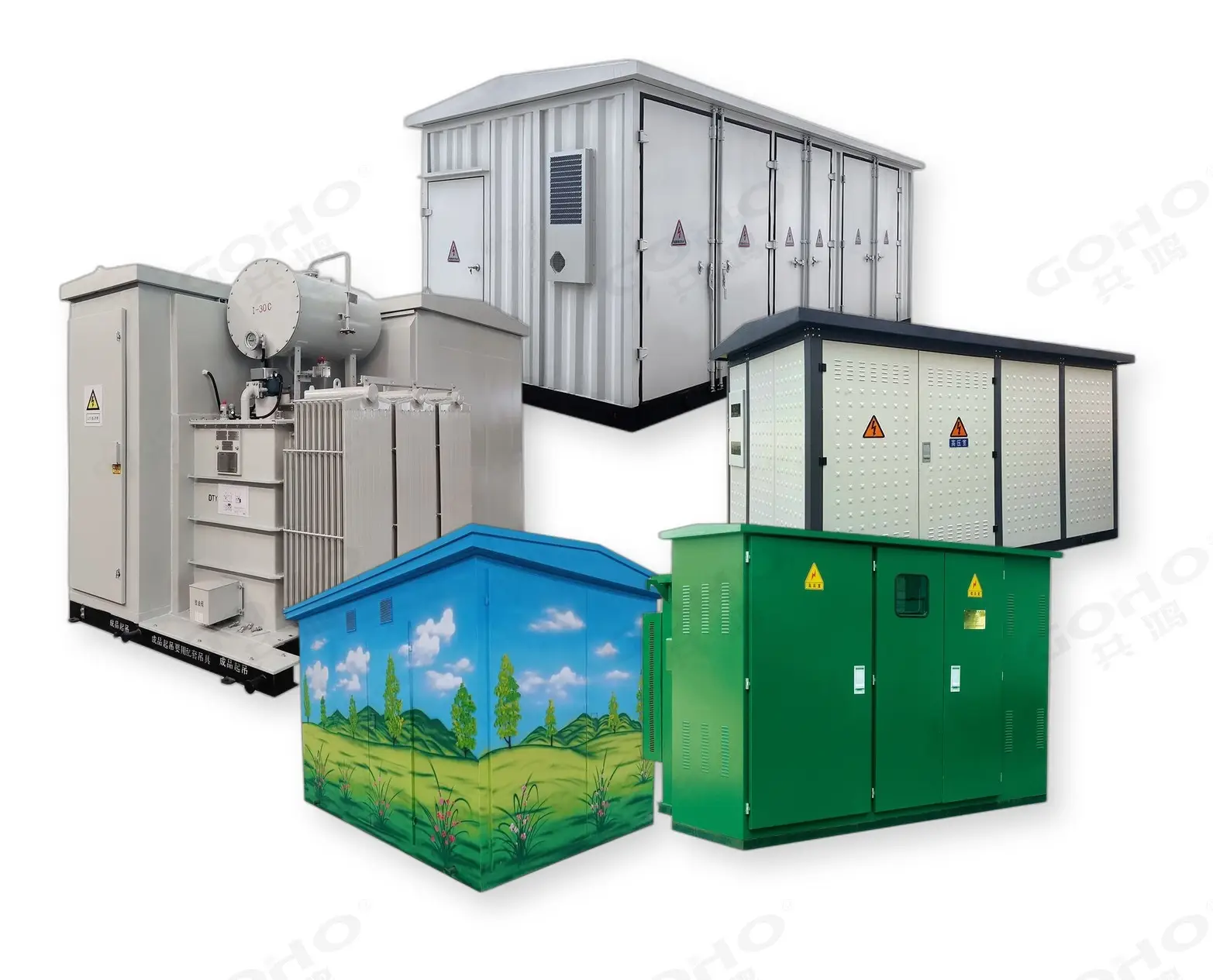
Complete Product Range
From 30 kVA distribution to 2500 kVA charging hub transformers
Comprehensive Testing
Every unit passes routine tests: ratio, resistance, insulation, and more
Frequently Asked Questions
Common questions about transformers for EV charging stations. Need more details? Contact our engineering team.
What size transformer do I need for an EV charging station?
Transformer size depends on total charger power, simultaneity factor, power factor, and harmonic content. As a starting point: a 500 kW station typically needs a 630 kVA transformer, a 1 MW station needs 1250 kVA, and a 2 MW station needs 2000 kVA. However, every site is different — the exact sizing must account for grid voltage, charger efficiency, diversity of use, and plans for future expansion. We recommend getting a free sizing calculation from our engineering team.
Why do EV chargers need a K-factor rated transformer?
DC fast chargers use rectifier circuits that draw non-sinusoidal current, creating harmonic distortion (typically THDi of 20–35%). Standard transformers are designed for linear (sinusoidal) loads and will overheat when serving harmonic-rich loads, leading to accelerated insulation aging and premature failure. K-factor rated transformers have oversized neutral conductors, specially designed winding geometry, and increased thermal capacity to handle harmonic heating without exceeding temperature limits. For EV charging, K-13 is the most commonly specified rating.
Oil-immersed or dry-type: which is better for EV charging?
It depends on the installation location and fire safety requirements. Oil-immersed transformers are more efficient, lower cost, and better for outdoor installations like highway rest stops and fleet depots. Dry-type transformers are safer for indoor use (no flammable oil), making them preferred for urban charging hubs, parking garages, and shopping malls. Dry-type units also require less maintenance but have higher upfront costs and slightly lower efficiency. For most outdoor EV charging sites, oil-immersed S13 or S22 units offer the best balance of performance and cost.
What is the warranty on GOHO EV charging transformers?
GOHO provides a standard 2-year warranty on all distribution transformers, covering manufacturing defects and workmanship. We also offer an optional extended warranty of up to 5 years for additional peace of mind. In the rare event of a warranty issue, our engineering team provides remote diagnostics and can arrange on-site support through our local service partners in many countries. All warranty claims are handled directly with the factory, ensuring fast resolution.
Can GOHO transformers be integrated into prefabricated substations?
Yes. In fact, this is our most popular configuration for EV charging stations. GOHO supplies complete prefabricated compact substations that integrate the MV switchgear (RMU or breaker), transformer, and LV distribution panel in a single weatherproof enclosure. These units are fully assembled, wired, and tested at the factory, dramatically reducing on-site installation time and cost. Standard designs range from 315 kVA to 2500 kVA, and we can customize the LV panel layout to match your exact charger configuration and cable entry points.
Get Your Free Transformer Sizing & Quote
Tell us your charging capacity and site conditions. We’ll recommend the right transformer within 24 hours.
Request a Free Quote →No obligation. Factory direct pricing from China.
Learn More About EV Charging Infrastructure
Dive deeper into transformer sizing, power distribution design, and charging station engineering.
EV Charging Station Transformer Sizing: Complete Calculation Guide
Step-by-step sizing methodology with formulas, worked examples, and selection criteria for DC fast charging infrastructure.
EngineeringEV Charging Station Power Distribution Design: Complete Guide
Complete engineering guide to power distribution system design for commercial DC fast charging hubs.
SolutionPrefabricated Substations for EV Charging: Complete Guide
How compact prefabricated substations reduce installation time and cost for EV charging station deployments.